
Page 162 - Practical Design Ships and Floating Structures
P. 162
137
3 RESULTS AND DISCUSSION
3.1 Static Trim Optimisation
The first objective of the work was to test the influence of the main hull trim and of the side-hull
position on the hydrodynamic resistance. Five trim positions of the main hull were tested (level trim 0",
aft trims + 0,5" and + lo, forward trims - 0,5" and -1"). The minimum resistance for high values of the
Froude number occurred at aft trim of + lo so all trimaran configurations have been subsequently
tested with this static trim.
3.2 Side Hull Positions
The tests on the optimisation of the trimaran side hull location were carried out with the outrigger hulls
derived from series 64 considering three lateral positions (clearances) y/L = 0.10; 0.1 1; 0.12 for a
given longitudinal position x/L = -0.0625 and four longitudinal positions (staggers) x/L = +0.25; 0; -
0.0625; - 0.125 for a given clearance y/L = 0.10 (fig. 2).
x/L = +O 25
I----
-------
Figure 2: Trimaran configuration; staggers and clearances.
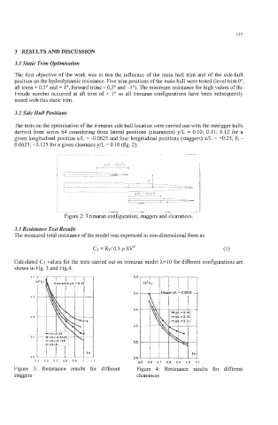
3.3 Resistance Test Results
The measured total resistance of the model was expressed in non-dimensional form as
CT = RT/ 0.5 p SV2 (1)
Calculated CT values for the tests carried out on trimaran model h=10 for different configurations are
shown in Fig. 3 and Fig.4.
50 5.5
1
5.0
45
4.5
40
4.0
35
3.5
Fn
30 3.0
05 06 07 08 09 1 11 0.5 0.6 0.7 0.8 0.9 1.0 1.1
Figure 3: Resistance results for different Figure 4: Resistance results for different
staggers clearances