
Page 155 - Practical Design Ships and Floating Structures
P. 155
130
buoyancy forces S are assumed as concentrated; in the only last case the hydrodynamic forces are
regarded as uniformly distributed on the middle part of the impacting hull.
+ The heaving hydrodynamic forces are always given by:
with : acgg= vertical acceleration in the centre of gravity. The pitch and roll hydrodynamic forces are
opposite and their moduli are assumed equal to Fh: Fp = Fr = Fh ; the pitch and roll moments are then
b L
given by A a - and A a - respectively, where b and L are the distance between the centrelines of
cg 2 cg 4
the two hulls, and the ship length.
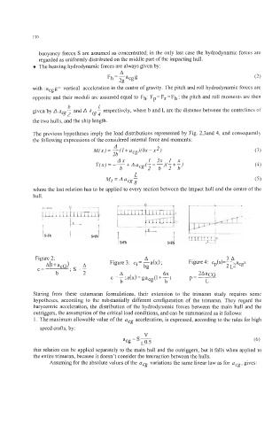
The previous hypotheses imply the load distributions represented by Fig. 2,3and 4, and consequently
the following expressions of the considered internal force and moments:
(3)
Ax 1 3 x l x
T(x)= ---iAaCg(~-~)(ji~) (4)
b
L
Mt = A acgs (5)
where the last relation has to be applied to every section between the impact hull and the centre of the
hull.
Figure 2: Figure 3: ci = -a(x); Figure4: c (x)=---a x
A
3A
A(l+acG) A bg P 2L2 cg
C= ; S=- 2
b A 6x 2AaCG
c = - ; a(x) = gacg(l + -1 b P = L
b
Staring from these catamaran formulations, their extension to the trimaran study requires some
hypotheses, according to the substantially different configuration of the trimaran. They regard the
barycentric acceleration, the distribution of the hydrodynamic forces between the main hull and the
outriggers, the assumption of the critical load conditions, and can be summarized as it follows:
1. The maximum allowable value of the acg acceleration, is expressed, according to the rules for high
speed crafts, by:
V
acg = S- ~0.5 (6)
this relation can be applied separately to the main hull and the outriggers, but it falls when applied to
the entire trimaran, because it doesn’t consider the interaction between the hulls.
Assuming for the absolute values of the acg variations the same linear law as for acg, gives: