
Page 171 - Practical Design Ships and Floating Structures
P. 171
146
high percentage of the residuary resistance (50-80%). This percentage increases with Fn. Anyway the
average percentage of the residuary resistance is about 25% of the total.
The interference phenomenon was also investigated for the optimised trimaran configuration. For this
purpose the wave pattern and the residuary non interference resistance coefficients were determined by
the expressions:
Were the suffix, codes T, M, 0 refer to trimaran, main hull and outrigger respectively.
The differences ACWP(T) = C wpq) - C* WP(T) and ACR(T) = C R(T) - C*R(T) between the resistance
coefficients of trimaran configuration and corresponding non interference resistance coefficients are
due to interference phenomenon. Figure 5 shows the percentages ACWP(T) /C*wp(~) and
ACR(T)/C*R(T) versus Fn. From the obtained results it can be seen that in the optimised configuration of
the examined trimaran, the wave making interaction between the main hull and the outriggers reduces
the wave resistance in the Fn range 0.70-1.00. The most beneficial interference results for Fn - 0.90,
and this value could be a reference in the design procedure of an operating trimaran.
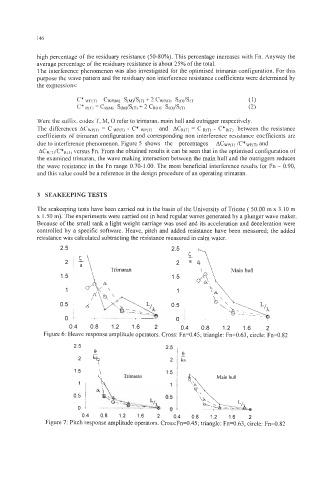
3 SEAKEEPING TESTS
The seakeeping tests have been carried out in the basin of the University of Trieste ( 50.00 m x 3.10 m
x 1.50 m). The experiments were carried out in head regular waves generated by a plunger wave maker.
Because of the small tank a light weight carriage was used and its acceleration and deceleration were
controlled by a specific software. Heave, pitch and added resistance have been measured; the added
resistance was calculated subtracting the resistance measured in calm water.
2.5 I 2.5 -,
Trimaran
i
1;
0.5 1
- ,
0 t ---- 0 I-. , ~ , . . ~
~
7- 7
0.4 0.8 1.2 1.6 2 0.4 0.8 1.2 1.6 2
Figure 6: Heave response amplitude operators. Cross: Fn=0.45; triangle: Fn=0.63, circle: Fn=0.82
2.5 , 2.5
l e le
2/ 2{G
0.4 0.8 1.2 1.6 2 0.4 0.8 1.2 1.6 2
Figure 7: Pitch response amplitude operators. Cross:Fn=0.45; triangle: Fn=0.63, circle: Fn=0.82