
Page 169 - Practical Design Ships and Floating Structures
P. 169
144
In order to minimis the total hydrodynamic resistance, a theoretical and experimental research on the
optimal position of the outriggers should be carried out with designed realistic hull forms and
dimensions of the main hull and of the outriggers.
The wave making interaction between the main hull and the outriggers has been investigated by model
tests. In addition, the wave pattern resistance of the isolated main hull, of the isolated side hull and of
the whole trimaran configuration have been measured using capacitive probes and applying the
longitudinal cut method, as proposed by Sharma (Eggers et al. 1967).
The seakeeping characteristics are also very important for the comparison among different ships,
therefore seakeeping tests were conducted both on the main hull and on the trimaran configuration.
The aim of this paper is to provide some hydrodynamic characteristics and to compare the considered
trimaran with equivalent monohull and catamaran ships.
2 RESISTANCE EXPERIMENTAL RESULTS
The resistance model tests were carried out on two geosims of a trimaran configuration which was
developed on the basis of the requested layout, of the limits due to service considerations and of data
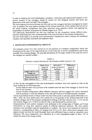
available from existing designs. The principal dimensions for the larger model of the main hull and of
the outrigger are reported in table 1.
TABLE 1
PRINCIPAL CHARACTERISTICS OF THE TRIMARAN MODEL (SCALE h=lO)
At first, for the investigation of the total hydrodynamic resistance, tests were carried out only on the
larger models for the following cases:
- several different static trim positions of the isolated main hull and of the outrigger to find the best
trim for the trimaran;
- several trimaran configurations (three different clearances and four staggers for a given clearance)
with the purpose to verify the influence of the side hull location on the hydrodynamic resistance.
All the experimental results of these model tests have been given in previous papers.(Bertorello et al.
2001). Then, the wave pattern tests were carried out on the geosims of the isolated main hull of the
isolated outrigger and of the trimaran configuration relating to the best clearance (yk = 0.12) and the
best realistic stagger (x/L=-0.0625) as shown in fig. 1 and determined by previous tests.
Measurements of wave pattern resistance were performed at the towing tanks of Naples and Trieste
Universities, by using four capacitive probes in different transverse positions. The wave pattern
resistance was calculated using the longitudinal cut method.. The waves were measured at transverse
distances y corresponding to ratios y/L ranging from 0.25 to 0.55; these values assure adequate wave
pattern records far from the model boundary layer and sufficiently long to avoid an immediate wave
reflection. The wave components were calculated up to wave propagation angles of about 85' to
include the most of the energy content.