
Page 178 - Practical Design Ships and Floating Structures
P. 178
153
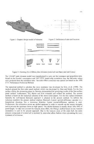
Figure 1 : Graphic design model of trimaran Figure 2: Definition of side-hull location
Figure 3: Drawing of a 2,500ton class trimaran (main hull and three side hull forms)
The 1A6.667 scale trimaran model was manufactured to carry out the resistance and propulsion tests.
Based on the Froude's assumption and 1957 ITTC model-ship correlation line, the full-scale values
were predicted from the resistance tests. The scale effect correction was carried out based on the 1978
ITTC Performance Prediction Method.
The numerical method to calculate the wave resistance was developed by Kim, et al. (1998). The
method adopted the first order panel method, which was developed by Hess and Smith. For the free
surface effects, the pioneering paper by Dawson demonstrated the promising results of the free-surface
panel method. Furthermore, Xia, Raven and Kim extended and refined the method. The present
method is based on the numerical schemes of the above-cited papers. For the free surface treatment
basically the well-known Dawson's approach is adopted in the present method. To enforce the
radiation condition the present method employs Dawson's 4-point upwind-difference operator in a
longitudinal direction. For a transverse direction 3-point central-difference operator is used.
Furthermore, the collocation points are shifted upstream in order to smooth out the source strengths
and to prevent the upstream waves at high speeds. The shifted distance is usually about 10%-30% of
panel length. To take into account the transom stem effect, the Cheng's method based on dry transom
assumption is used in the present approach. Due to the transom stem of the main hull, the static
pressure component of a main hull is included by somewhat adhoc fashion when calculating the wave
resistance of a trimaran.