
Page 180 - Practical Design Ships and Floating Structures
P. 180
155
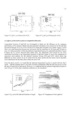
Figure 7: CR & CW at 18 knots (Fn=0.27) Figure 8: CR & CW at 30 knots (Fn=0.45)
4.2 Effects of Side-hull Location in Longitudinal Direction
Longitudinal location of side-hull was investigated to figure out the influence on the resistance
performance of the trimaran. Model tests and numerical calculations were carried out for the side-hull
location at Xs/Lpp=-O.15, 0.0, 0.15, 0.30 & 0.45 in length and Ys/Lpp=O.125 in beam. Figures 7 and 8
show very good agreement between the calculation and the experiment at 18 knots and 30 hots at
each. It is almost possible to select the optimum longitudinal location by numerical calculation. Figure
9 shows the CR curves obtained from model tests. The differences were caused by the wave
interference according to the longitudinal locations of side-hull. Figure 10 shows the comparison of
calculated wave patterns for the side-hull locations Xs/Lpp=O.36 and 0.075, which shows big
difference in wave system. It can be found from the wave system that the former shows favorable
wave interference but the latter shows nearly the worst case.
From the above results, it is found that the optimum longitudinal location is related with the ship's
speed. And the trimaran shows a favorable resistance performance when the side-hull moves toward
the stem of main hull at high speeds. However, it is supposed that the optimum longitudinal location is
near Xs/Lpp=O.3 if the ship's constraint conditions etc. are considered.
Figure 9: CR curves for side-hull locations in length Figure 10: Comparison of wave patterns