
Page 289 - Practical Design Ships and Floating Structures
P. 289
264
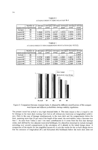
TABLE 2
AlTAINED INDEX A USING SOLAS PART B- 1
I 1 Number of 11 damage12 damage13 damage14 damage15 damage16 damage1
zones I zones I zones
Subdivision compartments zone zones zones zones zones zones
zones
As built 39 I 0.9742
As built
Layout #I 33 0.2626 0.5770 0.8107 0.9253 0.9676 0.9737
0.9676
0.2626
Layout #2 I 21 I 0.2626 0.5768 0.8061 0.9157 0.9562 0.9603
Layout #Z
21
0.2626
0.9562
Layout #3 I 13 I 0.2394 0.4928 I 0.6666 I 0.7381 0.751 1 0.7518
0.4928
0.2394
0.6666
13
0.7381
Layout #3
0.751 1
0.5398
0 1672
0.3325 I 0.4534 I 0.5148
#4
nvniit
I I I nvniit #4 I 11 I 0 1672 03325 0.4534 0.5148 0.5398 0.5445
11
TABLE 3
ATTAINED INDEX A USING HARMONISED REGULATIONS (SLF 43/3/2)
As buiit #I #2 #3 #4
Figure 2: Comparison between Attained Index A obtained by different simplifications of the compart-
ment layout and different probabilistic damage stability regulations
The present vessel has as-built a very high Attained Index A. The main reason is that s is equal to one
for damage to the main deck running from fore to att without any transverse or longitudinal subdivi-
sion. Only in the case of damage simultaneously to the main deck and the compartments below the
deck, spanning more than 20 per cent of the length of the vessel, the survivability index s becomes less
than 1. As seen from Tables 2 and 3 the main contributions to A come from the first four damage
zones, each defined by two adjacent transverse bulkheads. It is therefore important to include damages
extending over several compartments in the calculation of A already in the initial design phase. A
comparison of the results for the simplified layouts #1-4 with the results for the as-built design shows
that the omission of longitudinal (#1) and horizontal (#2) bulkheads below the main deck does not