
Page 352 - Practical Design Ships and Floating Structures
P. 352
327
The S-N curves are adopted with welded joint, and it is assumed that the structure is exposed to
corrosive effect of sour crude oil for half the ship life.
The fatigue damage can be calculated applying S-N curves for cathodic protection and corrosive
environment equally. Sim lified one-slope S-N curves have been used instead of bilinear curves with
P
change in slope beyond 10 cycles. Considering the load conditions and corrosion effect, the resultant
fatigue damage ratio leads to
Each pair of load cases is used to calculate stress range which is defined as the difference of minimum
and maximum stresses which are induced by minimum and maximum loading conditions, respectively.
Stress range for damage ratio calculation is defined based on notch stress [Wagner, 19981.
4.4 Fatigue Analysis of Longitudinal Stirener Connections
Fatigue analyses are performed in the connections of all longitudinal stiffeners except deck
longitudinals. The effective length of beam for calculating local bending is varied due to the detail
shape of longitudinal connections. Therefore, fatigue analyses for longitudinal connections are
performed in typical web frame section, swash BHD and transverse BHD separately. Fatigue
analyses for longitudinals at typical web frame section are performed in web h e section where
maximum stress occurs from the result of cargo tank analysis. Fatigue analysis for longitudinals at
transverse BHD are performed in fore and aft positions of the trans. BHD. FE model of 3-D cargo
tank analysis is employed to obtain relative deformation that would be used in fatigue damage
assessment of critical connections of longitudinal. The warping effect due to unsymmetrical section of
longitudinal stiffener is also considered in the calculation of stress components.
According to the result of fatigue analysis of longitudinal connections, fatigue lives of longitudinal
connections at aft position of transverse BHD are lower than longitudinal connections at fore position
of transverse BHD due to the larger effective length of longitudinal.
Longitudinal stiffeners around design draft have most severe fatigue strength because of the maximum
local bending stress due to external dynamic pressure. It can be found that all longitudinal stiffeners of
the subject vessel have sufficient fatigue strength.
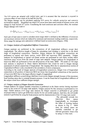
4.5 Fatigue Analysis of Hopper Knuckle Connection
Fatigue analysis for hopper knuckle connection is performed at the frame section having maximum
stress by the result of 3-D cargo tank analysis. Fatigue analysis for this structure is performed in two
steps. Global analysis (3-D cargo tank analysis for fatigue analysis) is performed to get global
structural behavior and to get deflections results for the sub-model analysis. And then, the sub-model
analysis is performed by using the local pressure and the displacements of the 3-D cargo tank model.
The sub-model extends two
transverse floor spaces
longitudinally to investigate
the effect of docking bracket
as shown in Fig. 3. Mesh
sizes for critical zones are
carefully controlled to get
relevant geometric stress even
by using t x t fine mesh.
Figure 3: Local Model for the Fatigue Analysis of Hopper Knuckle