
Page 349 - Practical Design Ships and Floating Structures
P. 349
324
al., 19991. In this paper, engineering of VLCC for improving productivity is suggested and the
development procedures for the new VLCC are introduced in the viewpoint of design.
2 STRUCTURAL ARRANGEMENT AND MID-SHIP SECTION
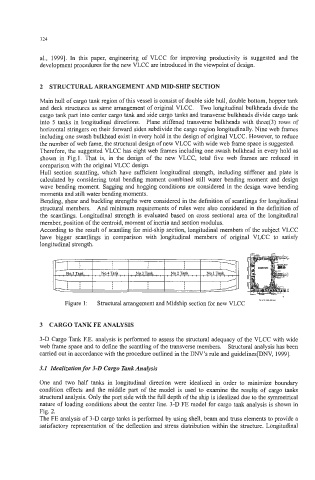
Main hull of cargo tank region of this vessel is consist of double side hull, double bottom, hopper tank
and deck structures as same arrangement of original VLCC. Two longitudinal bulkheads divide the
cargo tank part into center cargo tank and side cargo tanks and transverse bulkheads divide cargo tank
into 5 tanks in longitudinal directions. Plane stiffened transverse bulkheads with three(3) rows of
horizontal stringers on their forward sides subdivide the cargo region longitudinally. Nine web frames
including one swash bulkhead exist in every hold in the design of original VLCC. However, to reduce
the number of web fame, the structural design of new VLCC with wide web frame space is suggested.
Therefore, the suggested VLCC has eight web frames including one swash bulkhead in every hold as
shown in Fig.1. That is, in the design of the new VLCC, total five web frames are reduced in
comparison with the original VLCC design.
Hull section scantling, which have sufficient longitudinal strength, including stiffener and plate is
calculated by considering total bending moment combined still water bending moment and design
wave bending moment. Sagging and hogging conditions are considered in the design wave bending
moments and still water bending moments.
Bending, shear and buckling strengths were considered in the definition of scantlings for longitudinal
structural members. And minimum requirements of rules were also considered in the definition of
the scantlings. Longitudinal strength is evaluated based on cross sectional area of the longitudinal
member, position of the centroid, moment of inertia and section modulus.
According to the result of scantling for mid-ship section, longitudinal members of the subject VLCC
have bigger scantlings in comparison with longitudinal members of original VLCC to satisfy
longitudinal strength.
Figure 1 : Structural arrangement and Midship section for new VLCC
3 CARGO TANK FE ANALYSIS
3-D Cargo Tank F.E. analysis is performed to assess the structural adequacy of the VLCC with wide
web frame space and to define the scantling of the transverse members. Structural analysis has been
carried out in accordance with the procedure outlined in the DNV’s rule and guidelines[DNV, 19991.
3.1 Idealization for 3-0 Cargo Tank Analysis
One and two half tanks in longitudinal direction were idealized in order to minimize boundary
condition effects and the middle part of the model is used to examine the results of cargo tanks
structural analysis. Only the port side with the full depth of the ship is idealized due to the symmetrical
nature of loading conditions about the center line. 3-D FE model for cargo tank analysis is shown in
Fig. 2.
The FE analysis of 3-D cargo tanks is performed by using shell, beam and truss elements to provide a
satisfactory representation of the deflection and stress distribution within the structure. Longitudinal