
Page 345 - Practical Design Ships and Floating Structures
P. 345
320
EzHULL automatically identifies all loops to be boundary of faces. Then, a series of Euler operators
are applied for each loop, to construct the topology information. When this process is complete, the
topological information of the non-manifold data structure is completely constructed.
Finally, EzHULL generates the geometric information of the non-manifold data structure with only the
face boundaries. Since all surface patches are stored in the form of the tensor product NURBS in
EzHULL, only rectangular surface patches are allowed for the geometric information of faces[4,5].
However, triangular or pentagonal faces occur frequently in the hull form design, and therefore, a
degenerated NURBS surface patch is used for geometric data of the triangular faces. For pentagonal
faces, a new edge called a ‘hooking curve’ is inserted to subdivide the pentagonal face into two
rectangular faces as shown in Fig 4(C). After all faces are converted into rectangular faces, NURBS
surface patches can be generated with the four edges of the faces using the bilinearly blended Coons
patch method (Fig 4(D)). The bilinearly blended Coons patch can be easily converted to the
mathematically equivalent of the NURBS patch [5].
4.2 Application of Surface Model
The surface Model is mainly used for following three purposes.
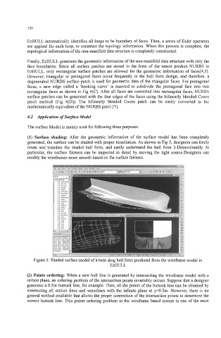
(1) Surface shading: After the geometric infomation of the surface model has been completely
generated, the surface can be shaded with proper tessellation. As shown in Fig 5, designers can freely
rotate and translate the shaded hull form, and easily understand the hull form 3-Dimensionally. In
particular, the surface fairness can be inspected in detail by moving the light source.Designers can
modify the wireframes more smooth based on the surface fairness.
Figure 5: Shaded surface model of a twin skeg hull form produced from the wireframe model in
EzHULL
(2) Points ordering: When a new hull line is generated by intersecting the wireframe model with a
certain plane, an ordering problem of the intersection points invariably occurs. Suppose that a designer
generates a 0.5m buttock line, for example. Then, all the points of the buttock line can be obtained by
intersecting all station lines and waterlines with the infinite plane at y=0.5m. However, there is no
general method available that allows the proper connection of the intersection points to determine the
correct buttock line. This points ordering problem in the wireframe based system is one of the most