
Page 343 - Practical Design Ships and Floating Structures
P. 343
318
improve the efficiency of hull form design [3]. This association means the relationship between X-
edges crossing each other, and X-edges of X-topology data structure are classified into three types: B-
line, S-line, and R-line according to the priority order of the association. The B-line is the X-edge that
has top priority, and is not affected by a change in any other line including other B-lines. Therefore, the
principal lines of the hull form are represented as B-lines. Since the S-line has second priority
compared to the B-line, it is affected by other B-lines, and the S-lines also affect each other. In other
words, if a B- or S-line is modified, all crossing Shes should be attached to it. When converting X-
topology to non-manifold data structure, the S-lines and B-lines are subdivided at their crossing points
into several curve segments that become boundary edges of surface patches. Finally, the R-line is
attached to B-line and S-lines by the lowest priority, and a change of an R-line cannot affect any other
line, including another R-line. So, the R-lines are usually used to describe the wireframe model in
detail.
3.2 Procedure of Cross Faring Based on Association
The cross faring based on the association is implemented by an ‘update line’ operation, which is
composed of several ‘touch line’ operations.
TouEh line operation Update operation
onWL08 , on ST15
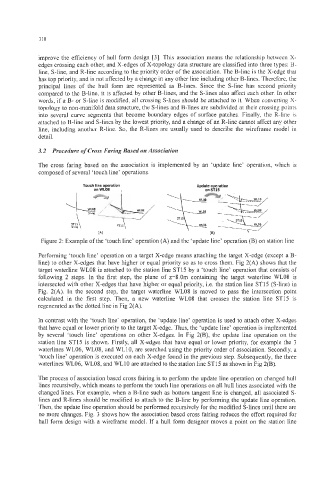
Figure 2: Example of the ‘touch line’ operation (A) and the ‘update line’ operation (B) on station line
Performing ‘touch line’ operation on a target X-edge means attaching the target X-edge (except a B-
line) to other X-edges that have higher or equal priority so as to cross them. Fig 2(A) shows that the
target waterline WL08 is attached to the station line ST15 by a ‘touch line’ operation that consists of
following 2 steps. In the first step, the plane of z=8.0m containing the target waterline WL08 is
intersected with other X-edges that have higher or equal priority, i.e. the station line ST15 (S-line) in
Fig. 2(A). In the second step, the target waterline WL08 is moved to pass the intersection point
calculated in the first step. Then, a new waterline WL08 that crosses the station line ST15 is
regenerated as the dotted line in Fig 2(A).
In contrast with the ‘touch line’ operation, the ‘update line’ operation is used to attach other X-edges
that have equal or lower priority to the target X-edge. Thus, the ‘update line’ operation is implemented
by several ‘touch line’ operations on other X-edges. In Fig 2(B), the update line operation on the
station line ST15 is shown. Firstly, all X-edges that have equal or lower priority, for example the 3
waterlines WL06, WL08, and WLlO, are searched using the priority order of association. Secondly, a
‘touch line’ operation is executed on each X-edge found in the previous step. Subsequently, the three
waterlines WL06, WL08, and WLlO are attached to the station line ST15 as shown in Fig 2(B).
The process of association based cross fairing is to perform the update line operation on changed hull
lines recursively, which means to perform the touch line operations on all hull lines associated with the
changed lines. For example, when a B-line such as bottom tangent line is changed, all associated S-
lines and R-lines should be modified to attach to the B-line by performing the update line operation.
Then, the update line operation should be performed recursively for the modified S-lines until there are
no more changes. Fig. 3 shows how the association based cross fairing reduces the effort required for
hull form design with a wireframe model. If a hull form designer moves a point on the station line