
Page 341 - Practical Design Ships and Floating Structures
P. 341
316
surfixe model through conceptual design, preliminaty design, and production design, it is necessary
for a hull form CAD system to provide following features.
Wireframe Cross Fairing: The cross fairing is a basic and essential feature in a wireframe based hull
design system. In the wireftame model, if one of crossing hull limes such as a station lii or a waterline
is modified for fairing, the other line should be altered to maintah the crossing points, this process is
called 'cross fairing' in hull form design. In addition to the crossing lines, all other lines that are
affected by them should also be rearranged automatically.
Direct Conversion from wireframe model to surface model: Hull form designers are used to dealing
with lines plan represented by a wirefkme model, and may estimate the jmformance of a ship based
on a wireframe model. On the other hand, they also require that the hull form surfaces be displayed to
check the surface fairness, Therefore, it is desirable to be able to perfom immediate conversion from
the wireframe model to the surface model to implement any necessary change into the wireframe
model even at the early design stages of the hull form.
Correct points ordering during wireframe generation: When a new hull line is generated by
intersecting a wirefixme model with a certain plane, an intersection points ordering problem always
occurs. Therefore, it is important to have the correct point ordering, especially with a complex multi-
hull form such as twin skeg hull.
In this research, a hull form CAD system called 'EzHULL' was developed to perform the above tasks.
Cross fairing features and conversion Erom wirewe model to surface model will be the main focus
of this paper, and we will also discuss how these features help to significantly reduce time and cost of
hull form design.
2 DATA STRUCTURE OF EZHULL
The data structure of EzHULL is composed of the wirehe and surface models that mutually
represent the hull form. The wireframe data struchue that efficiently supports the cross fairing is called
X-topology'. The non-manifold data structure is used for storing the surface model produced from the
wirefiame model.
2.1 X-toplogv Data Structure
The X-topology is a basic data structure for hull form design using the wirehe model. Hull form
designers usually perform cross fairing of the wirehme model by modifying the characteristic hull
lines, such as the station lime and the waterlime. If a fitting point is moved on a waterline, they expect
the waterline to be changed as a single unit curve and want the station lines crossing the waterline to
move in concert. In the non-manifold data structure, however, a single waterline and station line are
subdivided into several segments to represent edges that form face boundaries. Thus, in the EzHULL,
a data stcucture that can manipulate hull lis as a suitable unit and support effective cross fairing of
wireframe model has been developed and named 'X-topology', in addition to the non-manifold data
structure for the surface model.
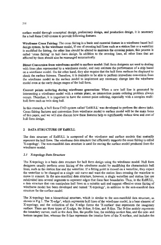
The X-topology has a hierarchical structure, which is similar to the non-manifold data structure, as
shown in Fig 1. The X-edge', which represents hull limes of the wirefiame model, is a base element of
X-topology, and the collection of the X-edge forms the 'X-surface' that represents the imaginary
surface. There are three types of X-edge, the B-line, S-line, and R-lime. The B-line mainly represents
the boundary curves, such as the deck line, the profile line, the midship section line, and the side- and
bottom tangent line, whereas the Wine represents the interior form of the X-surface, and includes the