
Page 368 - Practical Design Ships and Floating Structures
P. 368
343
Figure 1 : Concept of an information system for damages of ship structures
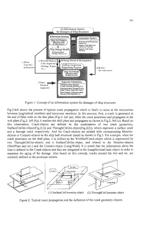
Fig.2-left shows the process of typical crack propagation which is likely to occur at the intersection
between longitudinal members and transverse members. In this process, first, a crack is generated at
the end of fillet weld on the face plate (Fig.2- left (a)). After the crack penetrates and propagates in the
web plate (Fig.2- left (b)), it reaches the shell plate and propagates as shown in Fig.2- left (c). Based on
this observation, Crack-objects are defined by the combination of two crack geometries,
SurfaceCrkGm-object(Fig.2( 1)) and ThroughCrkGm-object(Fig.2(2)), which represent a surface crack
and a through crack respectively. And the Crack-objects are related with corresponding Member-
objects or Connect-objects in the ship hull structural model as shown in Fig.3. For example, when the
crack penetrates on the shell plate, it is defined as the WebShellCrack-object which is represented by
two ThroughCrkGm-objects and a SurfaceCrkGm-object, and related to the Member-objects
(Shellplate and etc.) and the Connect-object (LongiWeld). It is noted that the information about the
time is defined in the Crack-objects and they are integrated in the LongiSectionCrack-object in order to
represent the aging of the damage. Also based on this concept, cracks around the slot and etc. are
similarly defined in the prototype system.
cpf=,f=g
Surface
.. _. -
Q~. ..
omf Point
(1) SurfaceCrkGeometry object
Figure 2: Typical crack propagation and the definition of the crack geometry objects