
Page 430 - Practical Design Ships and Floating Structures
P. 430
405
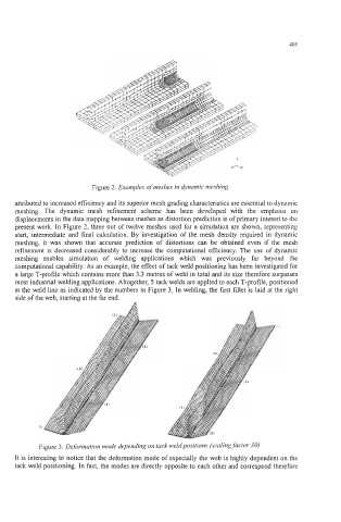
Figure 2: Examples of meshes in dynamic meshing.
attributed to increased efficiency and its superior mesh grading characteristics are essential to dynamic
meshing. The dynamic mesh refinement scheme has been developed with the emphasis on
displacements in the data mapping between meshes as distortion prediction is of primary interest to the
present work. In Figure 2, three out of twelve meshes used for a simulation are shown, representing
start, intermediate and final calculation. By investigation of the mesh density required in dynamic
meshing, it was shown that accurate prediction of distortions can be obtained even if the mesh
refinement is decreased considerably to increase the computational efficiency. The use of dynamic
meshing enables simulation of welding applications which was previously far beyond the
computational capability. As an example, the effect of tack weld positioning has been investigated for
a large T-profile which contains more than 3.3 metres of weld in total and its size therefore surpasses
most industrial welding applications. Altogether, 5 tack welds are applied to each T-profile, positioned
at the weld line as indicated by the numbers in Figure 3. In welding, the first fillet is laid at the right
side of the web, starting at the far end.
Figure 3: Deformation mode depending on tack weld positions (scaling factor 30)
It is interesting to notice that the deformation mode of especially the web is highly dependent on the
tack weld positioning. In fact, the modes are directly opposite to each other and correspond therefore