
Page 432 - Practical Design Ships and Floating Structures
P. 432
407
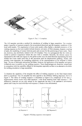
Figure 4: The L / G template
The WG template provides a method for simulation of welding in large assemblies. The template
makes it possible to represent properly the accumulated distortions and the boundary conditions of the
local solid models. The employment of local solid models offers further a detailed simulation of the
welding response as the local models include dynamic activation of fillet elements, dynamic coupling
of parts, the modelling of contact between parts and account for the positioning of tack welds. There
are, however, also drawbacks related to the WG template. First, it is presupposed that the welds are
cooled to ambient temperature before the next weld is initiated. Secondly, the stresses cannot be
represented in the weld line regions by the global model since the shell elements representing the local
models have been made stress-free in the procedure used for displacement updating. Thirdly, and
possibly most important, the modelling complexity of the implementation of the template is rather
large. The use of dedicated subroutines facilitates, however, the application of the template and makes
it relatively easy to modify e.g. the welding sequence. These disadvantages are, however, insignificant
in comparison with the capability offered by the template, especially as there is no alternative available
for welding simulation in large assemblies.
To illustrate the capability of the template the effect of welding sequence on the final displacement
field is considered. The L/G template has been applied to the arbitrary welding sequences shown in
Figure 5. The effect of welding sequence is illustrated in Figure 6 by comparison of the final y-
displacements which results from weld sequence 1 with those resulting from weld sequence 2. The
differences observed are not only related to the magnitude but also to the qualitative deformation
pattern and it may be concluded that weld sequence 2 results in less deformation.
(a) Sequence 1. (b) Sequence 2.
Figure 5 : Welding sequences investigated.