
Page 441 - Practical Design Ships and Floating Structures
P. 441
416
detach from the base of the transom junction for the former; a flow adheres to the transom for the latter.
Furthermore, a linear extrapolation for the wave height in the domain close to the transom is required
due to the discontinuity edge of the transom. The details of this approach are given by Li (2001).
3 SIMULATION OF THE TEST CASES
3.1 Mesh
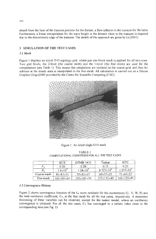
Figure 1 displays an initial 0-0 topology grid, where just one block mesh is applied for all test cases.
Two grid levels, the 2-level (the coarse mesh) and the I-level (the fine mesh) are used for the
computations (see Table 1). This means that simulations are initiated on the coarse grid, and then the
solution at the steady state is interpolated to the fine mesh. All calculation is carried out on a Silicon
Graphics Origin2000 provided by the Centre for Scientific Computing (CSC).
Figure 1 : An initial single 0-0 mesh
KCS DTMB 54 15 Tanker HTC
F" 0.26 0.28 0.15 0.25
lo7
R, 1.4~10~ 1.28~ 8.727~10~ 1.255~10~
.
Coarse mesh 8 1 x81 x3 1 97x81 x 17 69x57~25 71x65~23
Fine mesh 161x161~61 193x161~33 137x1 13x49 141x129~45