
Page 466 - Practical Design Ships and Floating Structures
P. 466
44 1
Figure 3: Axial velocity field at Station1 (x/Lpp = 0.95) at model scale (left) and full scale (right)
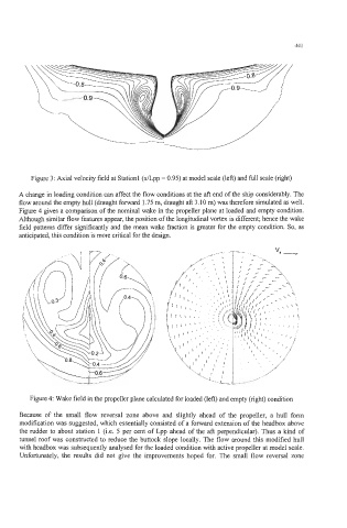
A change in loading condition can affect the flow conditions at the aft end of the ship considerably. The
flow around the empty hull (draught forward 1.75 m, draught aft 3.10 m) was therefore simulated as well.
Figure 4 gives a comparison of the nominal wake in the propeller plane at loaded and empty condition.
Although similar flow features appear, the position of the longitudinal vortex is different; hence the wake
field patterns differ significantly and the mean wake fraction is greater for the empty condition. So, as
anticipated, this condition is more critical for the design.
Figure 4: Wake field in the propeller plane calculated for loaded (left) and empty (right) condition
Because of the small flow reversal zone above and slightly ahead of the propeller, a hull form
modification was suggested, which essentially consisted of a forward extension of the headbox above
the rudder to about station 1 (Le. 5 per cent of Lpp ahead of the aft perpendicular). Thus a kind of
tunnel roof was constructed to reduce the buttock slope locally. The flow around this modified hull
with headbox was subsequently analysed for the loaded condition with active propeller at model scale.
Unfortunately, the results did not give the improvements hoped for. The small flow reversal zone