Page 477 - Practical Design Ships and Floating Structures
P. 477
452

              2  THEORY
              The right-handed Cartesian coordinate system as shown in Figure 1 is employed. The fluid field in the
              presence of a set of tandem fence is assumed steady, viscous and incompressible, which is represented
              by
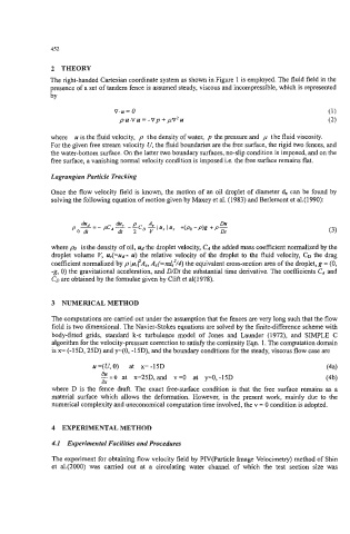
                              v-u= 0
                                pu.Vu = -vp +pv2u

              where  u is the fluid velocity,  p  the density of water,  p  the pressure and  p the fluid viscosity.
              For the given free stream velocity U, the fluid boundaries are the free surface, the rigid two fences, and
              the water-bottom surface. On the latter two boundary surfaces, no-slip condition is imposed, and on the
              free surface, a vanishing normal velocity condition is imposed i.e. the free surface remains flat.

              Lagrangian Particle Tracking
              Once the flow velocity field is known, the motion of an oil droplet of diameter 4 can be found by
              solving the following equation of motion given by Maxey et al. (1983) and Berlemont et a1.(1990):


              where po  is the density of oil, Ud the droplet velocity, CA the added mass coefficient normalized by the
              droplet volume V,  u,.(=ud-  u) the relative velocity  of the droplet to the fluid velocity, CD the drag
              coefficient normalized by p lurfAe, A,(=d;/4)  the equivalent cross-section area of the droplet, g = (0,
              -g, 0) the gravitational acceleration, and D/Dr the substantial time derivative. The coefficients CA and
              CD are obtained by the formulae given by Clift et al(1978).


              3  NUMERICAL METHOD

              The computations are carried out under the assumption that the fences are very long such that the flow
              field is two dimensional. The Navier-Stokes equations are solved by the finite-difference scheme with
              body-fitted  grids,  standard  k-E  turbulence  model  of  Jones  and  Launder  (1972), and  SIMPLE  C
              algorithm for the velocity-pressure correction to satisfy the continuity Eqn. 1. The computation domain
              is x= (-15D, 25D) and y==O,  -15D), and the boundary conditions for the steady, viscous flow case are

                         u=(U,O)  at  x=-15D                                          (44
                           ax
                           &=O   at  x=25D, and  v=O  at  y=O,-15D                   (4b)
              where  D is the  fence draft. The exact free-surface condition is that the free surface remains as a
              material surface which  allows the  deformation. However,  in the  present work,  mainly due to the
              numerical complexity and uneconomical computation time involved, the v = 0 condition is adopted.


              4  EXPERIMENTAL METHOD
              4.1  Experimental Facilities and Procedures

              The experiment for obtaining flow velocity field by PIV(Partic1e Image Velocimetry) method of Shin
              et  al.(2000) was  carried  out  at  a  circulating water  channel  of  which  the  test  section  size  was

