
Page 482 - Practical Design Ships and Floating Structures
P. 482
457
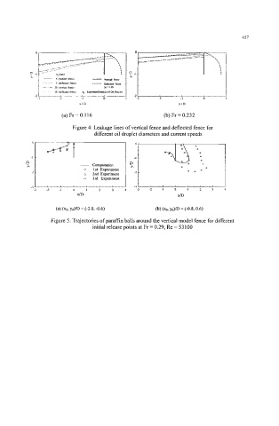
(a)Fr=0.116 (b) Fr = 0.232
Figure 4: Leakage lines of vertical fence and deflected fence for
different oil droplet diameters and current speeds
I- 4 1
E! - Cornputstion
h
0 1st Experiment
2
A 2ndExpenment
0 3rd E-ment
Figure 5: Trajectories of pdin balls around the vertical model fence for different
initial release points at Fr = 0.29, Re = 53 100