
Page 504 - Practical Design Ships and Floating Structures
P. 504
479
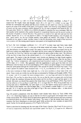
Here the origin for x.y and zis on the centreplane at the waterplane amidships. L,Band T are
respectively the length, beam and draught, where BIL = 0.1 and TIL = 0.0625 in our case. We
divided the centreplane into panels and the source density on each panel was taken as constant and
equal to its value at the middle of the panel. Convergence studies were done by using different number
of panels and the wave resistance results obtained by Eq. (5) were compared with results by Eq. (8).
We used either 50( 10 x 5), 120(20 x 6) or 240(30 x 8) panels to calculate the wave resistance. Here the
first number in the brackets is the number of panels in longitudinal direction and the second number is
the number of panels in vertical direction. The panel size is small at bow and stem and near the free
surface. Results for HIL = 0.1 are shown in Table 2. For high Froude numbers, even 50 panels can
give good results, but for low Froude number, more panels are needed. One reason is that the
resistance at low speed is small. Another reason is that the decreasing wave length of the transverse
wave systems with decreasing speed requires more panels in the longitudinal direction.
In Fig 2, the wave resistance coefficient Cw = -24 IpU2S in deep water and finite water depth
Hl L = 0.1 are presented. Here S is the area of the mean wetted hull surface. When 8 is less than
-0.6, the influence of water depth is small. The reason is that the wave lengths associated with the far-
field wave systems are small relative to the depth and the waves cannot be influenced by the sea floor.
We can also see from Fig 1 that the wave angle is almost the same as that in deep water. The influence
of the sea floor is large close to the critical speed ( Fh = 1). At high Froude numbers, the influence is
small again. The reason is that the divergent wave systems are dominant for high Froude numbers.
Since the wave lengths of the divergent wave systems are small, the influence from the sea floor is
small. Fig 3 shows comparisons with experimental and theoretical results by Everest and Hogben
(1 970) when H / L = 0.425. The agreement with the experiments is quite good but there are some
differences with the theory by Everest and Hogben (1970). There is no great change of wave resistance
when the speed passes through the critical speed. This can also be clearly seen from Figs 4 and 5. Figs
4 and 5 present the shallow water resistance ratio r = R, I R, as a function of HI L and Fh . Here R,,
is the wave resistance in finite water depth and R, is the wave resistance in deep water at the same
speed. These results are similar but not the same as presented by Hofman and Kozarski (2000). When
F,, is near 1 and H / L is small, the wave resistance ratios r are very large and cannot be clearly seen
from Fig 4. We use Fig 5 to show these results. We can see that the wave resistance ratio can be larger
than 50 when the clearance between the ship bottom and the sea flour is small and the speed is near
critical. Obviously we should then question the linear theory (Lea and Feldman (1972)). Fig 4 shows
that the influence of the sea floor is small when H / L is larger than 0.4. When doing model tests in a
towing tank such as MARINTEK, the water depth is 5.5 m, the highest towing speed is about 8 ds.
The depth Froude number may then be larger than 1. If for instance a model length L=5.5 m is used,
the ratio H / L =1 and the curve lies at far right of Fig 4. The wave resistance ratio r is then almost
equal to 1 even near the critical speed.
Figs 6-8 present comparisons with the shallow water slender body theory by Tuck (1966) when
HI L = 0.1. From those figures, we can see that the two theories agree quite well except in the vicinity
of the critical speed. The vertical force at supercritical speed and the pitch moment and wave resistance
at subcritical speed are zero by slender body theory. The reason is that the slender body theory only
considers the local disturbance at subcritical speed while predicts the wave systems at supercritical
speed. Further the for and aft symmetry of the Wigley hull matters.
Wash is calculated by keeping only the wave part of the Green’s function. Figs 9 and 10 show pictures
of wash at respectively subcritical and supercritical speed. For Fig 9, Fh is equal to 0.9. Measured