
Page 507 - Practical Design Ships and Floating Structures
P. 507
482
0.m - /---,
c
om -
0.w
I 0
03
02 03 04 05 06 07 08 n 01 02 H IL 0.4 05
0307 0460 0614 0767 0820 1074 1227Fh
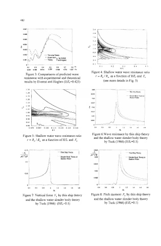
Figure 3: Comparisons of predicted wave Figure 4: Shallow water wave resistance ratio
resistance with experimental and theoretical r = R, 1 R, as a function of HIL and F,
results by Everest and Hogben (H/L=0.425) (see more details in Fig. 5)
1.15 1201 \ I 0.02s { I
0 03
I10
2
IO5
I 00
0 95
0 90 0.010 0.085 0.100 0.115 0.130 0.145 0.160 04 06 08 I 12 14 16 18
0 85
I
-zr Figure 6:Wave resistance by thin ship theory
0 80
HIL
Fh
Figure 5: Shallow water wave resistance ratio
and the shallow water slender body theory
r = R, I R, as a function of HIL and Fh
by Tuck (1 966) (WL=O. 1)
0.025
-minshipTheny
I
0.
’
I
- - Slcnda Body Theory in N’L’B
0.02
Shallow water
O.OI5
0.01
o . 0 5 p
0.005
0.
0.4 0.6 08 I 1.2 1.4 1.6 1.8
Fh
Figure 7: Vertical force F3 by thin ship theory
and the shallow water slender body theory
by Tuck (1966) (H/L=O. 1)