
Page 95 - Practical Design Ships and Floating Structures
P. 95
70
Figure 2: Example surface patch arrangement
3.2 Parametric Design Approach
The modelling technique presented in this paper is based on a parametric curve generation approach
developed by Harries and Abt (1997) and has been successfully utilized for the generation and
automated optimisation of bare hulls by Harries (1998). The method utilizes a parametric curve
generation process where the vertices of all B-spline curves are computed from a geometric
optimisation, employing fairness criteria as measures of merit and capturing global shape
characteristics as equality constraints. Properties of the hull, such as the shape of the centerplane curve
or the shape of the deck for instance, are represented as curves created from form parameters.
Parametric curves - e.g. for the flare angle or the submerged sectional area - reflect the properties of
the sectional shape of the ship at any longitudinal position. Once this set of so-called basic curves is
created from the specified input, a numerical algorithm is applied to create a set of sections at selected
locations and, subsequently, a skinning (Woodward 1988) is performed to create a surface definition
from the skeleton of design sections. A suitable arrangement of design sections is determined
automatically from an analysis of the basic curves.
The geometric modelling system developed by the authors - called FRIENDSHIP-Modeler - is based
entirely on parametric principles. The parameterisation is implemented on the basis of a user-readable,
marine design-oriented model-file. An excerpt of a model-file is depicted in Figure 3.
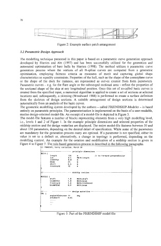
The model-file features a number of blocks representing elements from a very high modelling level,
Le., levels 1 and 2 of Figure 1. In the example principle dimensions and selected properties of the
midship section and the design waterline are displayed. The entire model-file features between 30 and
about 150 parameters, depending on the desired detail of specification. While some of the parameters
are mandatory for the generation process many are optional. If a parameter is not specified, either its
value is set to a default or, alternatively, a change in topology is performed, depending on the
modelling context. An example for the creation and modification of a midship section is given in
Figure 4 to Figure 7. The rule-based generation process is described in the following paragraphs.
// PRRDSil1. ferry uariation. March M I
length 176 m I/ to forward perpendicular
lax 1.5 MIN.length
lenOfPar 1.1 m
beam 25 m
draft 6.5 m
freeboard 12 m
.....
...
.-
I
Figure 3: Part of the FRIENDSHIP model file