
Page 94 - Practical Design Ships and Floating Structures
P. 94
69
optimisation process is achieved. In order to improve this situation the new method of hull modelling
is developed such that the design-oriented parameters are directly translated into a mathematical hull
representation. New geometry generation procedures based on hierarchical rules ensure variability and
applicability of the approach.
3 MODELLING APPROACH
Traditional CAD-based geometric modelling is characterized by employing mathematically defined
curves and surfaces which are manipulated by means of a graphical user interface (GUI). The model
generally consists of a considerable number of free variables which have to be modified in a highly
concerted manner. The initial set-up of a feasible arrangement of entities requires knowledge about
both the ships topology of appearance and the mathematics of its representation. Once the set-up is
done for a specific hull form, global changes cannot be accomplished easily and modifications of
functional parameters remain time-consuming tasks.
3. I Requirements of the Mathematical Representation
For further utilization within the design process a complete geometric model - in the meaning of a
computer internal representation (CIR) - is required. CAD-models based on B-spline technology are
employed successfully in many marine-related software packages. The B-splines' advantageous
characteristics with regard to local shape control, internal continuity and variability makes them a
powerful element for all kind of shape representations.
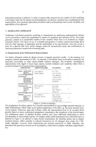
Level:
Specification:
Vocabulary:
Applied language:
.............................................
TOOO~O~Y of eg TEU,
Appccrance speed, CGT
may beav
'crgth, draft I
engsie type
propeller
_____-----_---------------------
eg xcb,
xcf disp
rad1 angles 2
-ariycnts
_____----___------_-------------
eg vertex
Represerltation coordinates, 3
weights, patc h
arrangement
---___-------------_____________________-----
Figure 1 : Levels of topology
The arrangement of surface patches for a feasible representation of a given shape depends basically on
shape characteristics which make up the general appearance of the hull, e.g. flat areas, knuckle lines,
curved regions. Moreover, gaps and overlaps within the representation have to be avoided which
possibly leads to a more complicated arrangement, depending on the complexity of the desired shape.
The quadrilateral nature of standard B-spline surfaces may cause additional subdivisions to avoid
discontinuities in unfavourable regions. An example surface patch arrangement for a fast RoRo-ferry is
depicted in Figure 2. In addition to these formal requirements, the resulting surface has to display
excellent fairness, which normally is realized interactively by the designer who creates the CAD-
model. Manually, however, these requirements are typically non-trivial to fulfil. Naturally, any
automated hull generation process has to accomplish a result which complies with these requirements,
too.