
Page 89 - Practical Design Ships and Floating Structures
P. 89
64
.-
~
dl 0.2 0.4 0.6
0.1
0.2 ' design dra
..
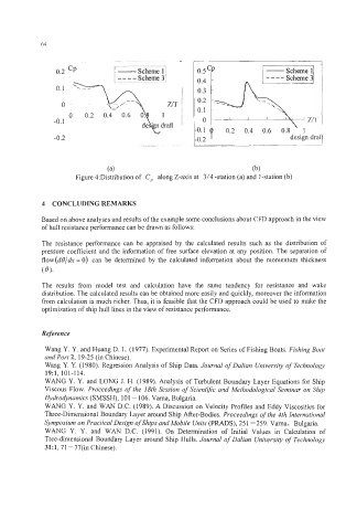
Figure 4:Distribution of C, along Z-axis at 3/4 -station (a) and 1-station (b)
4 CONCLUDING REMARKS
Based on above analyses and results of the example some conclusions about CFD approach in the view
of hull resistance performance can be drawn as follows:
The resistance performance can be appraised by the calculated results such as the distribution of
pressure coefficient and the information of free surface elevation at any position. The separation of
flow(dQ/dw = 0) can be determined by the calculated information about the momentum thickness
(0).
The results from model test and calculation have the same tendency for resistance and wake
distribution. The calculated results can be obtained more easily and quickly, moreover the information
from calculation is much richer. Thus, it is feasible that the CFD approach could be used to make the
optimization of ship hull lines in the view of resistance performance.
Reference
Wang Y. Y. and Huang D. L. (1977). Experimental Report on Series of Fishing Boats. Fishing Boat
and Port 2, 19-25 (in Chinese).
Wang Y. Y. (1980). Regression Analysis of Ship Data. Journal of Dalian University of Technology
19~1, 101-114.
WANG Y. Y. and LONG J. H. (1989). Analysis of Turbulent Boundary Layer Equations for Ship
Viscous Flow. Proceedings of the 18th Session of Scientific and Methodological Seminar on Ship
Hydrodynamics (SMSSH), 101 - 106. Varna, Bulgaria.
WANG Y. Y. and WAN D.C. (1989). A Discussion on Velocity Profiles and Eddy Viscosities for
Three-Dimensional Boundary Layer around Ship After-Bodies. Proceedings of the 4th International
Symposium on Practical Design of Ships and Mobile Units (PRADS), 25 1 -259. Varna, Bulgaria.
WANG Y. Y. and WAN D.C. (1991). On Determination of Initial Values in Calculation of
Tree-dimensional Boundary Layer around Ship Hulls. Journal of Dalian University of Technology
31:1,71-77(in Chinese).