
Page 86 - Practical Design Ships and Floating Structures
P. 86
61
2.3 Optimization of Local Hull Lines (Level 2)
Reynolds Average Navier-Stokes (RANS) equations with 2-turbulence model and linear free surface
boundary condition, together with the differential numerical approach (Wang and Wan, 1991; Wang
and Wang, 1994; Wang and Wang, 1995; and Wang and Wang, 1996) are applied to simulate flow
around ship hull in time domain. The objective functions are the viscous resistance coefficient and the
wave-making resistance coefficient, with the local hull lines being the optimization object.
2.4 Optimization of Appendage Lines (Level 3)
Partly-parabolic type of Navier-Stokes equations with 2-turbulence model by use of differential
numerical approach with the pressure marching or the finite-volume method (Wang and Cai, 1998; Li,
Lin and Wang, 1997; Li, Lin and Wang, 1998) is used to simulate flow considering the interaction
between hull and propeller. The objective functions are the viscous resistance (coefficient) and the
wake fraction and the optimized objects are local hull lines, appendage lines and propeller set.
2.5 Optimization of Finalizing Hull Lines (Level 4)
Model test is employed to confirm the optimization result. In fact the information both for the
optimized model and for the modification of tested model can be obtained from the computations
based on Level 2 and 3.
At present the relative accuracy of predicting resistance performance by using CFD code can be
ensured, that means it could be used to make comparison with different models. But the final
prediction of hull resistance should be determined by use of model test. Up to now the CFD code can
predict the resistance performance of ship hull with model size (Re = 106-7) and thus the model test
can be camed out under the same scale of computational model. The prediction of resistance
performance for a ship with full scale (generally Re = lo8-’) should consider the scale effects.
Ship designers hope that the resistance performance could be directly predicted by a suitable CFD
code, and hence the requirement of model test could be minimized. However this objective may only
be partly achieved for some of series ships and for ships that have support from big relative database.
For new ship form developing the model test is necessary and all of CFD’s results must be validated by
model tests.
3 APPLICATION
DSMT tanker model as an example of optimization process is provided as follows. The optimization of
Level 2 has been made after Level 0 and 1.
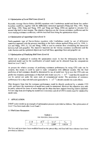
3.1 Hull Lines Parameters
TABLE 1
THE PRINCIPAL PARAMETERS
5.5 3 I 0.009 I 0.8158
The bow and stem have been modified based on the parent ship, and four hull lines schemes have been
provided as follows: