
Page 81 - Practical Design Ships and Floating Structures
P. 81
56
0
Panels are limited by their lateral edges (junctions with other panels, AA" and BB") either by
watertight bulkheads or transverse frames. These panels are orthotropic plates and shells supported
on their four sides, laterally loaded (bending) and submitted, at their extremities, to in-plane loads
(compressiodtensile and shearing).
Global buckling of panels (including the local transverse frames) must also be considered.
Panel supports, in particular those corresponding to the reinforced frames, are assumed infinitely
rigid. This means that they can distort themselves significantly only after the stiffened panel
collapse.
on the transverse
0
The frames take the lateral loads (pressure, dead weight, etc.) and are therefore submitted to
combined loads (large bending and compression). The rigidity of these frames must be assured in
order to respect the hypotheses on panel boundary conditions (undeformable supports).
0 e (box glrder/hull PirderL
The ultimate strength of the global structure or a section (block) located between two rigid frames
(or bulkheads) must be considered as well as the elastic bending moment of the hull girder (against
yielding).
The limit states that will be considered are:
- A service limit state that corresponds to a situation where the structure can no longer assure the
service for which it was conceived (examples: excessive deflection cracks).
- An ultimate limit state that corresponds to collapselfailure.
It is important to differentiate service limit states to ultimate limit states because safety factors
associated to these two limit states are generally different.
Global siwcmre (or pan ofthc srmcturc between Z bulkheads)
VI A
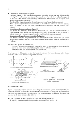
w Structural modelling of the structure
Figure 5:
Lcuel2 The whole pan4 (alffcnedionhalroplc panel) and its components.
4.1 Ultimate Limit States
Figure 5 presents the different structure levt.,: the global structure or general structure (level I), the
orthotropic stiffened panel (level 2) and the interframe longitudinally stiffened panel and its simplified
modelling: the beam-column (level 3 and 3bis). The relations between the different limit states and
structure levels can be summarised as follows:
.) Level 1 : Ultimate bending moment of the global structure (hull girder): Mu
.) Ultimate strength of compressed orthotropic stiffened panels ( IJ J.