
Page 79 - Practical Design Ships and Floating Structures
P. 79
54
sub-module for each constraint type. To date, only a limited number of modules are available (in
general 1 or 2 for each constraint type). It is up to the user to complete, adapt and add new modules
according to his specific requirements (type of structure, codes and regulations to be followed,
technical and scientific level, available hardware, etc.). The objective is to enable the user himself to
build the tool he needs.
Figures 1 and 2 show the basic configuration of the LBR-5 software with the 3 fundamental modules
(COST, CONSTRAINT and OPTI) and the "DATABASES" in which the user can do his "shopping",
i.e. chbose the relevant constraints and cost data. After selecting the geometrical and structural
constraints and cost assessment tools in the databanks.
3 DESCRIPTION OF THE 3 BASIC MODULES: OPTI, CONSTRAINT AND COST
The problems to be solved can be summarised as follows:
xi i = 1, N, the N design variables,
F(Xi) the objective function to minimize,
m Cj(Xi) I CM, j = 1 ,M the M structural and geometrical constraints,
XiminSXi 5 Xima upper and lower bounds of the Xi design variables:
technological bounds (also called side Constraints).
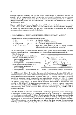
The structure (Figure 3) is modelled with stiffened panels (plates and cylindrical shells). For each
panel one can associate up to 9 design variables (Xi). These 9 design variables are respectively:
Plate thickness (I),
For longitudinal members (stiffeners,
crossbars, longitudinals, girders, etc.):
- web height and thickness (2, 3),
- flangewidth(4,
- spacing between 2 longitudinal members (
For transverse members (fnunes, etc.):
- web height and thickness(6, 7),
- flange width (8),
- spacing between 2 transverse frames (9). Figure 3: Basic stiffened panel (or basic element).
The OPTI module (Figure 2) contains the mathematical optimization algorithm (CONLM) that
allows solving non-linear constrained optimization problems. It is especially effective because it only
requires a reduced number of iterations. In general, fewer than 15 iterations (including a structure re-
analysis) are necessary, even in presence of several hundred design variables (Xi). CONLN is based
on a convex linearization of the non-linear functions (constraints and objective functions) and on a
dual approach (Fleury 1989). This module uses as inputs the resultdoutputs of the two other basic
modules, i.e. CONSTRAINT for the C(Xi) constraints and COST for the F(Xi) objective function. Due
to the choice of a dual algorithm (CONLIN), the treatment of side constraints (Xi min and Xi ,=) is
particularly easy. Thus we can dissociate them from other constraints (C, (Xi) I CM,), which is
particularly attractive.
The COST module: In 2001, even for a first draft, a least weight optimization process can no longer
be justified and should be replaced by a least construction cost or, even better, by a minimum global
cost (including operational costs). To link the objective function (Euro) to the design variables (Xi), the
unit costs of raw materials (EuroKg), the productivity rates for welding, cutting, assembling, etc.
(man-hourslunit of work = m-Wunit) and labour costs (Euro/m-h) must be specified by the user (Rig0
2001-c). These unit costs vary according to the type and the size of the structure, the manufacturing
technology (manual welding, robots, etc.), the experience and facilities of the construction site, the