
Page 74 - Practical Design Ships and Floating Structures
P. 74
49
wave drag reduction for the optimal center hull (B) at high Froude numbers is not as pronounced as
that for the optimal center hull (A). Similarly, the optimal outer hull (A) is obtained by minimizing
Ck(F) for one Froude number, P0.35, and the optimal center hull (B) is obtained by minimizing
Ck(F) for two values of Froude number, F0.3, 0,35. Fig. 3b depicts the predicted wave-drag-
coefficient curves corresponding to the original outer hull and two optimal outer hulls. Fig. 3b
indicates that the optimal outer hull (B) has a larger wave drag reduction than that of the optimal outer
hull (A) over almost the entire speed range in comparison to the original outer hull. Therefore, the
optimal outer hull (B) and the optimal center hulls (A) and (B) will be used further on as two optimal
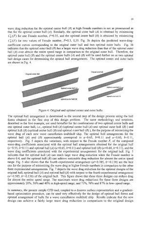
hull design cases for determining the optimal hull arrangements. The optimal center and outer hulls
are shown in Fig. 4.
Dngmal center hull
Figure 4: Original and optimal center and outer hulls
The optimal hull arrangement is determined in the second step of the design process using the hull
forms obtained in the first step of this design problem. The same methodology and notations,
described in the first example, are used hereafter for the combinations of two optimal center hulls and
one optimal outer hull, i.e., optimal hull (A) (optimal center hull (A) and optimal outer hull (B) ) and
optimal hull (B) (optimal center hull (B) and optimal outer hull (B) ), for the purpose of minimizing the
wave drag of each new wave cancellation multihull ship. The optimal hull arrangements for the
optimal hull (A) and (B) approximately correspond to a=0.65, b=0.11 and a=0.60, b=0.11,
respectively. Fig. 5 depicts the variations, with respect to the Froude number F, of the computed
wave-drag coefficients associated with the optimal hull arrangements obtained for the original hull
(a=0.55, b=0.11) and optimal hull (A) (a=0.65, b=0.11) and optimal hull (B) (a=0.60, b=0.1 l), and the
wave drag coefficients associated with the experimental arrangements for the original hull. Fig. 5
indicates that the optimal hull (A) can reach large wave drag reduction when the Froude number is
above 0.4, and the optimal hull (B) can achieve noticeable drag reduction for almost the entire speed
range. Fig. 5 also shows that the fourth experimental arrangement (a=-0.385, b=-0.136) are the best
one for the purpose of minimizing the wave drag at higher Froude numbers in comparison to the other
three experimental arrangements. Fig. 7 depicts the wave drag reduction for the optimal designs of the
original hull, optimal hull (A) and optimal hull (B) with respect to the fourth experimental arrangement
(a=-0.385, k0.136) of the original hull. This figure shows that these three designs can reduce drag
for almost the entire speed range. The maximum wave drag reductions for these three designs are
approximately 20%, 56% and 40% in high-speed range, and 71%, 76% and 87% in low- speed range.
In summary, the present simple CFD tool, coupled to a discrete surface representation and a gradient-
based optimization procedure, can be used very effectively for the design of optimal hull forms and
optimal arrangement of hulls for a wave cancellation multihull ship. Results indicate that the new
design can achieve a fairly large wave drag reduction in comparison to the original design