
Page 73 - Practical Design Ships and Floating Structures
P. 73
48
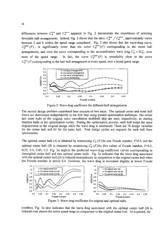
differences between CF and Cy"' apparent in Fig. 2 demonstrate the importance of selecting
favorable hull arrangements. Indeed, Fig. 2 shows that the ratio, C," / C,- , approximately varies
between 2 and 6 within the speed range considered. Fig. 2 also shows that the wave-drag curve,
CT"'(F) , is significantly lower than the curve CT"'(F) corresponding to the worst hull
arrangements, and even the curve corresponding to the no-interference wave drag Ci +2Ci, over
most of the speed range. In fact, the curve C,""'(F) is remarkably close to the curve
Cp (F) corresponding to the best hull arrangement at every speed, over a broad speed range.
40 -
3 ::. - Cw m t arrangements
35 '
8 20.
8 15.
10.
05.
00 1
Figure 2: Wave drag coefficient for different hull arrangements
The second design problem considered here consists of two steps. The optimal center and outer hull
forms are determined independently in the first step using present optimization technique. The center
and outer hulls of the original wave cancellation multihull ship are used, respectively, as starting
baseline hulls in the optimization cycles. During the optimization process, each hull keeps the same
displacement as the original design while the wave drag is minimized. There are 76 design variables
for the center hull and 64 for the outer hull. Four design cycles are required for each hull form
optimization.
The optimal center hull (A) is obtained by minimizing Ci (F) for one Froude number, F=0.5, and the
optimal center hull (B) is obtained by minimizing Cg(F)for five values of Froude number, F=0.3,
0,35, 0.4, 0.45, 0.5. Fig. 3a depicts the predicted wave-drag-coefficient curves corresponding to
theoriginal center hull and two optimal center hulls. Fig. 3a indicates that the wave drag associated
with the optimal center hull (A) is reduced tremendously in comparison to the original center hull when
the Froude number is above 0.4. However, the wave drag is increased slightly at lower Froude
1.4 1.4
1.2 1.2
+Cw optid canter hull (A)
1.0 1.0
g 0.8 8 0.8
- - 0.6
0
g 0.6
0.4 0.4
0.2 0.2
0.0 0.0
02 025 03 035 04 045 05 055 02 025 03 035 04 045 05 055
Froude number Froude number
Figure 3: Wave drag coefficient for original and optimal hulls
numbers. Fig. 3a also indicates that the wave drag associated with the optimal center hull (B) is
reduced over almost the entire speed range in comparison to the original center hull. As expected, the