
Page 72 - Practical Design Ships and Floating Structures
P. 72
47
2 and the related functions A, AR and A’ given by Eqn. (3e) similarly need to be evaluated only once
per Froude number.
6 NUMERICAL RESULTS AND CONCLUSIONS
The first design problem considered here is to determine the optimal hull arrangement for the original
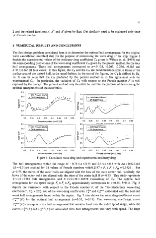
wave cancellation multihull ship for the purpose of minimizing the wave drag of the ship. Figure I
depicts the experimental values of the residuary drag coefficient CR given in Wilson et. al. (1993) and
the corresponding predictions of the wave-drag coefficient CW given by the present method for the four
hull arrangements. These hull arrangements correspond to a=-0.128, -0.205, -0.256, -0.385 and
b=O.136 for all four cases. In this figure, the C, and the CW are nondimensionalized in terms of the
surface area of the wetted hull, in the usual fashion. In the rest of the figures, the CW is defined by Eq.
la. It can be seen that the CW predicted by the present method is in fair agreement with the
experimental CR. In particular, the variation of CR with respect to the Froude number F is well
captured by the theory. The present method may therefore be used for the purpose of determining the
optimal arrangements of the outer hulls.
2.5
’
2.0
2 1.5
8 1.0
r
0.5
0.5
0.0
0.2 0.25 0.3 0.35 0.4 0.45 0.5 0.55 0.0 4
Fmude number (a=-0.128) 0.2 0.25 0.3 0.35 0.4 0.45 0.5 0.55
2.5 7 2.5 I
+* +
’
0.5
0.0 J 0.0 J I
0.2 0.25 0.3 0.35 0.4 0.45 0.5 0.55 0.2 0.25 0.3 0.35 0.4 0.45 0.5 0.55
Froude number (ai0.256) Froude number (a-4.385)
Figure 1 : Calculated wave drag and experimental residuary drag
The hull arrangements within the range of -0.75Ia10.75 and 0.11b10.3 with Aa=O.O25and
Ab = 0.01 are studied for 38 values of Froude numbers with0.2147 = F, IF, IF,, = 0.5426 . For
a=0.75, the stems of the outer hulls are aligned with the bow of the main center hull; similarly, the
bows of the outer hulls are aligned with the stem of the center hull if r-0.75. This study represents
61 x 21 = 1281 hull arrangements and 61 x 21 x 38 = 48678 evaluations of CW. The optimal hull
arrangement for the speed range F, I F, 1 F3* approximately corresponds to n=0.55, b=O. 11. Fig. 2
depicts the variations, with respect to the Froude number F, of the “no-interference wave-drag
coefficient”, C& + 2Ci and of the wave-drag coefficients CF and associated with the best and
worst hull arrangements found within the region. Fig. 2 also shows the wave drag-coefficient curve
CLp’”’(F) for the optimal hull arrangement (a=0.55, b=0.11). The wave-drag coefficient curve
C~!””’(F) corresponds to a hull arrangement that remains fixed over the entire speed range, while the
curves CF(F)and Cy‘(F)are associated with hull arrangements that vary with speed. The large