
Page 80 - Practical Design Ships and Floating Structures
P. 80
55
country, etc. It is therefore obvious that the result of this optimization process (sizing optimization)
will be valid only for the specific economic and production data under consideration. Sensitivity
analysis of the economic data on the optimum scantling can also be performed, thus providing the
manager with valuable information for improving the yard.
The CONSTRAINT module (see next section) helps the user to select relevant constraints within
constraint groups at his disposal in a databank (Figure 1). In fact, the user remains responsible for his
choice. However, in order to facilitate this selection, several coherent constraint sets are proposed to
the user. These sets are based on national and international ruleskodes (Eurocodes, ECCS
Recommendations, Classification Societies, etc.). The user must first choose the types of constraints
(yielding, buckling, deflection, etc.) then, for each type of constraint, select the method, the code or the
&to use and finally the points/areas/mels where these constraints will be applied.
4 STRUCTURAL AND GEOMETRICAL CONSTRAINTS
Constraints are linear or non-linear functions, either explicit or implicit of the design variables (Xi).
These constraints are analytical “translations” of the limitations that the user wants to impose on the
design variables themselves or to parameters like displacement, stress, ultimate strength, etc. Note that
theseparameters are functions of the design variables. So one can distinguish:
- Technological constraints (or side constraints) that provide the upper and lower bounds of the
design variables (for example: Ximi,, = 4mm I Xi < Xi,, = 40 mm).
- Geometrical constraints impose relationships between design variables in order to guarantee a
functional, feasible, reliable structure. They are generally based on “good practice” rules to avoid
local strength failures, or to guarantee welding quality and easy access to the welds. For instance,
welding a plate of 30 mm thick with one that is 5 mm thick is not recommended.
- Structural constraints represent limit states in order to avoid yielding, buckling, cracks, etc. and to
limit deflection, stress, etc. These constraints are based on solid-mechanics phenomena and
modelled with rational equations. By rational equations, we mean a coherent and homogeneous
group of analysis methods based on physics, solid mechanics, strength and stability treatises, etc.
and that differ from empirical and parametric formulations.
The list of the structural constraints included in the LBR-5 model is intimately bound to the types of
structures targeted by this research. Let’s recall that these are mainly metallic, prismatic (box girders)
and stiffened (orthotropic) structures used for hydraulic and marine structures. These structures are
composed of stiffened panels that are either cylindrical or plane. The panels are joined one to another
by generating lines (edges of the prismatic structure) and are stiffened longitudinally and transversely
(Fig. 7). A‘
d
Stiffened longitudinallv:
- by stiffeners,
and/or
- by crossbars and girders, prompt A
elements of strong rigidity.
Stiffened transversely:
- by transverse bulkheads,
andlor
- by the main transverse framing, B
and/or
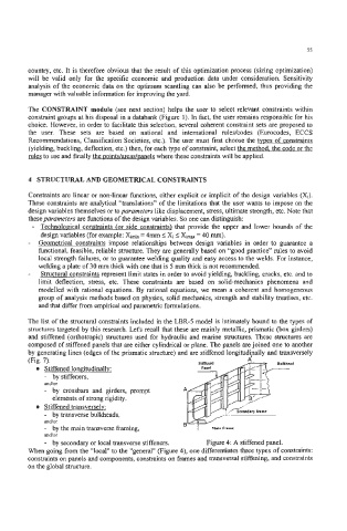
- by secondary or local transverse stiffeners. Figure 4: A stiffened panel.
When going from the “local” to the “general“ (Figure 4), one differentiates three types of constraints:
constraints on panels and components, constraints on frames and transversal stiffening, and constraints
on the global structure.