
Page 87 - Practical Design Ships and Floating Structures
P. 87
62
Scheme 1 : the parent ship of DSMT tanker
Scheme 2: the DSMT tanker with modified bow (raising the center of gravity of bulbous bow)
Scheme 3: the DSMT tanker with modified stem (increasing the value of alb )
Scheme 4: the DSMT tanker with modified bow (raising the center of gravity of bulbous bow) and
modified stem (increasing the value of a1 b)
TABLE 2
PRINCIPAL DIMENSIONS OF BOW AND STERN FOR 4 SCHEMES
I Scheme 1 I Scheme2 1 Scheme3 I Scheme4
BlockCoefficient C. I 0.8158 1 0.8159 I 0.8159 I 0.8160
4 11, 0.16 0.16 0.16 0.16
Parameter hblT 0.489 0.485 0.489 0.485
of Bow b,. lB 0.1684 0.169 0.1684 0.169
sp Is 0.00607 0.00612 0.00607 0.00612
Parameter alb 0.4 12 0.4 12 0.538 0.538
of Stem hb lh. 1 .oo 1 .oo 1 .oo 1 .oo
Zb /I, : the ratio of length of bulbous bow to length between perpendiculars.
hb IT : the ratio of distance from draft to the position where bulbous bow is widest to design draft.
b,, 1 B : the ratio of the maximum width of bulbous bow at zero station to molded breadth.
sp /s : the ratio of the transection area of bulbous bow at zero station to the midship section area.
b
a/ : the ratio of the minimum width to the maximum width at the defined station of the bulb stem.
hb 1 h, : the ratio of the height of the bulb stem's center to that of the propeller's axis above the baseline.
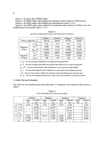
3.2 Model Test and Calculation
The model test and calculation have been made under 15°C freshwater. The results have been shown in
Table 3.
TABLE 3
DATA FOR MODEL TEST AND CALCULATION