
Page 169 - Practical Machinery Management for Process Plants Major Process Equipment Maintenance and Repair
P. 169
Positive Displacement and Dynamic Blowers 151
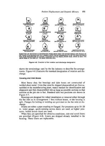
COUMER-CLOCKWISE CLOCKWISE CLOCKWISE COUNTERGLOCKWISE
Top IIORRONTAL Top NORIZONTAL SmOM HORIZONTAL BOlTOH. HORliONlIL
el 0 c KWISE COUNlER.CLOCKWISE CLOCKWISE
UP BLAST UP EWT DOWN EUST
C0WER.C Q LOCKWISE
CLOCKWISE CLOCKWISE COUNTER.CLOCI(WISE
8
TOPANQULAR WWN TOCANGUUR M)ww BMTOM ANnULAR UP BOTTOM ANGULAR UP
COUWIERGLOCKWlSE CLOCKWISE CLOCKWISI CDUNTERCLOCKWISE
TOP ANQUUR UP TOP ANQUUR UP BOlTO1 ANQULAR DOWN BOTTOM ANGULAR DOWN
DIRECTION OF ROTATION IS DETERMINED FROM DRIVE SIDE FOR EITHER SINOLE OR DOUBLE IN.
LET FANSOHE DRIVING SIDE OF A SINGLE INLET FAN IS CONSIDERED TO BE THE SIDE OPPOSITE
THE INLET REGARDLESS OF ACTUAL LOCATION OF THE DRIVE.) WHEN DUAL DRIVE IS USED THE
DRIVE SIDE IS THE SIDE OF THE MAIN DRIVING UNIT.
Figure 4-6. Direction of fan rotation and discharge designation.
shows the terminology used by the fan industry to describe fan arrange-
ments. Figure 4-6 illustrates the standard designation of rotation and dis-
charge.
Housing and Inlet Boxes
Most heavy duty fan housings and inlet boxes are constructed of
welded sheet metal. Units that must be shipped disassembled are first as-
sembled at the manufacturing plant, match marked for identification and
alignment and then disassembled into as large as possible sections so that
erection at the job site is fast. Standard inlet box positions are shown in
Figure 4-7.
Housings are designed for wheel installation or removal either through
the fan inlet as in Arrangement 1 fans without boxes, or the housing is
split. Flanges for bolting or welding are provided on the fan inlet or dis-
charge.
Drains are either a pipe coupling or flanged. For pressures up to 18-20
in. water gauge, quick-opening access doors are used; at higher pres-
sures, bolted access doors are used.
When fans are specified for abrasive conditions, side and scroll liners
are provided (Figure 4-8). Liners are shipped already installed in the
housing. These liners are replaceable.