
Page 179 - Practical Machinery Management for Process Plants Major Process Equipment Maintenance and Repair
P. 179
Positive Displacement and L3ynamic Blowers 161
OUTER RlNO OF FLOATINQ
OUTER RlNO OF FLOATINQ
DEARINQ
DEARINQ MUST BE LOCATED MUST BE LOCATED
1 1
SECTION
UPPER SECTION
2 2 HOWS BEARING FLOATINQ
RING FLOATINQ
10
10
5 5
11
11
7 7
4
OF OVERFLOW
9
8
3 OWER SECTION
SHOWS BEARINQ FIXED
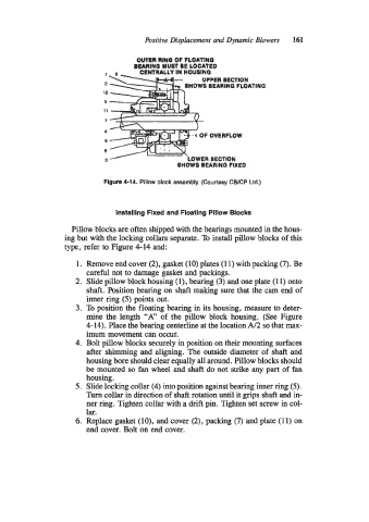
Figure 4-14. Pillow block assembly. (Courtesy CWCP Ltd.)
Installing Fixed and Floating Pillow Blocks
Pillow blocks are often shipped with the bearings mounted in the hous-
ing but with the locking collars separate. To install pillow blocks of this
type, refer to Figure 4-14 and:
1. Remove end cover (2), gasket (10) plates (1 1) with packing (7). Be
careful not to damage gasket and packings.
2. Slide pillow block housing (l), bearing (3) and one plate (1 1) onto
shaft. Position bearing on shaft making sure that the cam end of
inner ring (5) points out.
3. To position the floating bearing in its housing, measure to deter-
mine the length “A” of the pillow block housing. (See Figure
4- 14). Place the bearing centerline at the location A/2 so that max-
imum movement can occur.
4. Bolt pillow blocks securely in position on their mounting surfaces
after shimming and aligning. The outside diameter of shaft and
housing bore should clear equally all around. Pillow blocks should
be mounted so fan wheel and shaft do not strike any part of fan
housing.
5. Slide locking collar (4) into position against bearing inner ring (5).
Turn collar in direction of shaft rotation until it grips shaft and in-
ner ring. Tighten collar with a drift pin. Tighten set screw in col-
lar.
6. Replace gasket (lo), and cover (2), packing (7) and plate (1 1) on
end cover. Bolt on end cover.