
Page 184 - Practical Machinery Management for Process Plants Major Process Equipment Maintenance and Repair
P. 184
166 Major Process Equipment Maintenance and Repair
mi enpansion of the shaft. If motor incoprates sleave bear-
ings use a limited end float coupling to restrict movement.
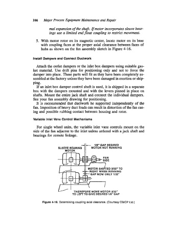
5. With motor rotor on its magnetic center, locate motor on its base
with coupling faces at the proper axial clearance between faces of
hubs as shown on the fan assembly sketch in Figure 4-16.
Install Dampers and Connect Ductwork
Attach the outlet dampers or the inlet box dampers using suitable gas-
ket material. Use drift pins for positioning only and not to force the
damper into place. These parts will fit as they have been completely as-
sembled at the factory unless they have been damaged in erection or ship-
ping.
If an inlet box damper control shaft is used, it is shipped in a separate
box with the dampers mounted and with the levers pinned in place on
shafts. Mount the entire jack shaft and connect the individual dampers.
See your fan assembly drawing for positioning.
It is recommended that ductwork be supported independently of the
fan. Imposition of heavy duct loads can result in distortion of the fan cas-
ing and possible rubbing contact between housing and rotor.
Variable Inlet Vane Control Mechanisms
For single wheel units, the variable inlet vane controls mount on the
side of the fan adjacent to the inlet unless ordered with a jack shaft and
bearings for remote linkage.
MOTOR il-
118” GAP DESIRED
SLEEVE BEARING MOTOR NOT RUNNING
THEREFORE MOVE MOTOR 3/32”
TO LEFTTO GIVE DESIRED 118” GAP
Figure 4-18. Determining coupling axial clearance. (Courtesy CWCP La.)