
Page 186 - Practical Machinery Management for Process Plants Major Process Equipment Maintenance and Repair
P. 186
168 Major Process Equipment Maintenance and Repair
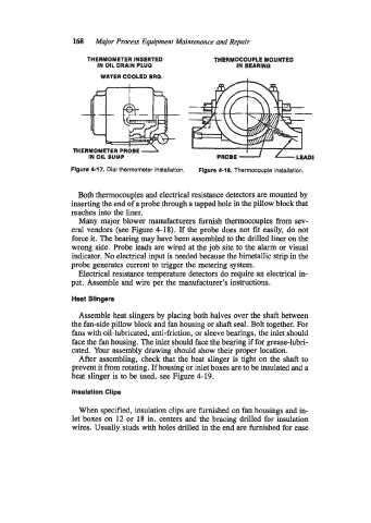
THERMOMETER INSERTED THERMOCOUPLE MOUNTED
IN OIL DRAIN PLUG IN BEARINQ
WATER COOLED BRO.
IN OIL SUMP PROBE U J / a
flgure 4-17. Dial thermometer installation. Figure 4-18. Thermocouple installation.
Both thermocouples and electrical resistance detectors are mounted by
inserting the end of a probe through a tapped hole in the pillow block that
reaches into the liner.
Many major blower manufacturers furnish thermocouples from sev-
eral vendors (see Figure 4-18). If the probe does not fit easily, do not
force it. The bearing may have been assembled to the drilled liner on the
wrong side. Probe leads are wired at the job site to the alarm or visual
indicator. No electrical input is needed because the bimetallic strip in the
probe generates current to trigger the metering system.
Electrical resistance temperature detectors do require an electrical in-
put. Assemble and wire per the manufacturer’s instructions.
Heat Slingers
Assemble heat slingers by placing both halves over the shaft between
the fan-side pillow block and fan housing or shaft seal. Bolt together. For
fans with oil-lubricated, anti-friction, or sleeve bearings, the inlet should
face the fan housing. The inlet should face the bearing if for grease-lubri-
cated. Your assembly drawing should show their proper location.
After assembling, check that the heat slinger is tight on the shaft to
prevent it from rotating. If housing or inlet boxes are to be insulated and a
heat slinger is to be used, see Figure 4-19.
Insulation Clips
When specified, insulation clips are furnished on fan housings and in-
let boxes on 12 or 18 in. centers and the bracing drilled for insulation
wires. Usually studs with holes drilled in the end are furnished for ease