
Page 197 - Practical Machinery Management for Process Plants Major Process Equipment Maintenance and Repair
P. 197
Reciprocating Gas Engines and Compressors 179
--CRA&K END
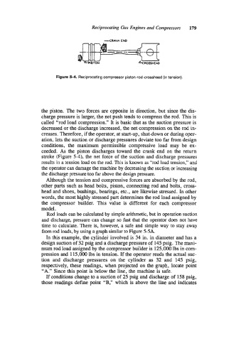
Rgure 54. Reciprocating compressor piston-rodcrosshead (in tension).
the piston. The two forces are opposite in direction, but since the dis-
charge pressure is larger, the net push tends to compress the rod. This is
called “rod load compression.” It is basic that as the suction pressure is
decreased or the discharge increased, the net compression on the rod in-
creases. Therefore, if the operator, at start-up, shut-down or during oper-
ation, lets the suction or discharge pressures deviate too far from design
conditions, the maximum permissible compressive load may be ex-
ceeded. As the piston discharges toward the crank end on the return
stroke (Figure 5-4), the net force of the suction and discharge pressures
results in a tension load on the rod. This is known as “rod load tension,” and
the operator can damage the machine by decreasing the suction or increasing
the discharge pressure too far above the design pressure.
Although the tension and compressive forces are absorbed by the rod,
other parts such as head bolts, piston, connecting rod and bolts, cross-
head and shoes, bushings, bearings, etc., are likewise stressed. In other
words, the most highly stressed part determines the rod load assigned by
the compressor builder. This value is different for each compressor
model.
Rod loads can be calculated by simple arithmetic, but in operation suction
and discharge, pressure can change so fast that the operator does not have
time to calculate. There is, however, a safe and simple way to stay away
from rod loads, by using a graph similar to Figure 5-5A.
In this example, the cylinder involved is 34 in. in diameter and has a
design suction of 32 psig and a discharge pressure of 145 psig. The maxi-
mum rod load assigned by the compressor builder is 125,000 lbs in com-
pression and 115,000 lbs in tension. If the operator reads the actual suc-
tion and discharge pressures on the cylinder as 32 and 145 psig,
respectively, these readings, when projected on the graph, locate point
“A.” Since this point is below the line, the machine is safe.
If conditions change to a suction of 25 psig and discharge of 158 psig,
those readings define point “B,” which is above the line and indicates