Page 193 - Practical Machinery Management for Process Plants Major Process Equipment Maintenance and Repair
P. 193

Positive Displacement and Llynamic Blowers   175

                    6.  Use a split bushing to push the packing to the bottom of the box.
                       Seat the ring firmly by replacing the gland and taking up on the
                       bushing.  Seat this bottom ring hard,  because this first ring does
                       most of the sealing.
                     7.  Repeat with each packing ring, making sure to stagger the joints
                       90" apart.
                     8.  If  a lantern ring is used, position it properly under the grease or
                       purge hole(s) in the box.
                    9.  After the last ring is installed, position the gland and finger tighten
                       the bolts.
                    10. Break the packing in (refer to Volume 3 of this series).

                 Checking hrlabie inlet Vane Poaltlon

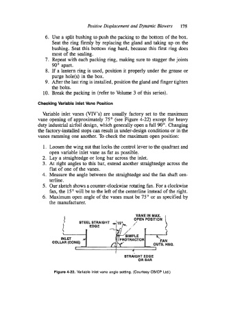
                   Variable inlet vanes (VIV's)  are usually factory set to the maximum
                 vane opening of approximately 75" (see Figure 4-22) except for heavy
                 duty industrial airfoil design, which generally open a full 90". Changing
                 the factory-installed stops can result in under-design conditions or in the
                 vanes ramming one another. To check the maximum open position:

                    1.  Loosen the wing nut that locks the control lever to the quadrant and
                      open variable inlet vane as far as possible.
                   2.  Lay a straightedge or long bar across the inlet.
                   3.  At right angles to this bar,  extend another straightedge across the
                      flat of one of the vanes.
                   4.  Measure the angle between the straightedge and the fan shaft cen-
                      terline  .
                   5.  Our sketch shows a counter-clockwise rotating fan. For a clockwise
                      fan, the 15" will be to the left of the centerline instead of the right.
                   6.  Maximum open angle of the vanes must be 75" or as specified by
                      the manufacturer.
                                                                  2!
                                   STEEL STRAIQHT 8  2!
                                                            VANE IN MAX
                                                                   MAX
                                                            VANE
                                                                IN
                                                           OPEN
                            {  1  1  I ,                   OPEN POSlTlON
                                                                POSlTlON
                                         STRAIQHT
                                   STEEL
                                 ,
                            {
                                        EDGE  -I  EDGE
                                                       SIMPLE
                                                       SIMPLE
                           INLET                     PROTRACTOR
                                                     PROTRACTOR
                           INLET
                              (CONE)
                          .LAR
                        COI .LAR (CONE)                            OUTS. HSQ.
                                                                        HSQ.
                                                                   OUTS.
                                                       STRAIGHT EDGE
                                                       STRAIGHT  EDGE
                                                             OR BAR
                                                             OR  BAR
                        Figure 4-22. Variable inlet vane angle setting. (Courtesy CB/CP Ltd.)
   188   189   190   191   192   193   194   195   196   197   198