
Page 198 - Practical Machinery Management for Process Plants Major Process Equipment Maintenance and Repair
P. 198
180 Major Process Equipment Maintenance and Repair
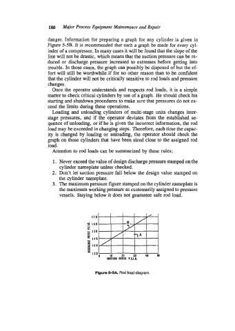
danger. Information for preparing a graph for any cylinder is given in
Figure 5-5B. It is recommended that such a graph be made for every cyl-
inder of a compressor. In many cases it will be found that the slope of the
line will not be drastic, which means that the suction pressure can be re-
duced or discharge pressure increased to extremes before getting into
trouble. In those cases, the graph can possibly be disposed of but the ef-
fort will still be worthwhile if for no other reason than to be confident
that the cylinder will not be critically sensitive to rod loads and pressure
changes.
Once the operator understands and respects rod loads, it is a simple
matter to check critical cylinders by use of a graph. He should check his
starting and shutdown procedures to make sure that pressures do not ex-
ceed the limits during these operations.
Loading and unloading cylinders of multi-stage units changes inter-
stage pressures, and if the operator deviates from the established se-
quence of unloading, or if he is given the incorrect information, the rod
load may be exceeded in changing steps. Therefore, each time the capac-
ity is changed by loading or unloading, the operator should check the
graph on those cylinders that have been sized close to the assigned rod
load.
Attention to rod loads can be summarized by these rules:
1. Never exceed the value of design discharge pressure stamped on the
cylinder nameplate unless checked.
2. Don’t let suction pressure fall below the design value stamped on
the cylinder nameplate.
3. The maximum pressure figure stamped on the cylinder nameplate is
the maximum working pressure as customarily assigned to pressure
vessels. Staying below it does not guarantee safe rod load.
170
3 160
H
Y
2 I50
.L
Y
140
Y
u
I
-
a 130
H
10
20
JO
e SOtllOl PRESS RS.1.G. 40 50
Figure 5-M. Rod load diagram.