
Page 430 - Practical Machinery Management for Process Plants Major Process Equipment Maintenance and Repair
P. 430
48 Major Process Equipment Maintenance and Repair
OIL LEVEL INDICATOR
CONNECTINQ
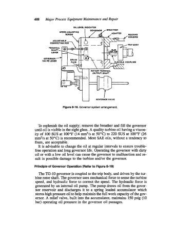
Figure 8-18. Governor system arrangement.
To replenish the oil supply; remove the breather and fill the governor
until oil is visible in the sight glass. A quality turbine oil having a viscos-
ity of 100 SUS at 100°F (14 m*/s at 50°C) to 220 SUS at 100°F (26
mm2/s at 50°C) is recommended. Most SAE oils, without a tendency to
foam, are acceptable.
It is advisable to change the oil at regular intervals to ensure trouble-
free operation and long governor life. Operating the governor with dirty
oil or with a low oil level can cause the governor to malfunction and re-
sult in possible damage to the turbine and/or the governor.
Principle of Governor Operation (Refer to Figure 8-19)
The TGlO governor is coupled to the trip body, and driven by the tur-
bine rotor shaft. The governor uses mechanical force to sense the turbine
speed, and hydraulic force to correct the speed. The hydraulic force is
generated by an internal oil pump. The pump draws oil from the gover-
nor reservoir and discharges it to a spring loaded accumulator which
stores high pressure oil to help maintain the full work capacity of the gov-
ernor. A relief valve, built into the accumulator, maintains 150 psig (10
bar) operating oil pressure in the governor oil passages.