
Page 463 - Practical Machinery Management for Process Plants Major Process Equipment Maintenance and Repair
P. 463
440 Major Process Equipment Maintenance and Repair
The torque to be applied to the screws used in the reassembly of the
machine can be found in the following torque table issued by the manu-
facturer.
lnspectlon and Allowable Wear Data
Check journal, thrust bearings, and shaft.
The maximum allowable clearances are given in Table 8-11. Carefully
examine bearings and thrust washer faces for score marks. If scoring is
excessive, replace them with new parts. It is recommended that all seals
and seal inserts be replaced.
The dynamic balance of shaft, expander rotor and compressor impeller
should also be checked in accordance with the tabulated figures. The ro-
tating assembly components have been accurately machined and dynami-
cally balanced; to check the balance of the assembly or to follow align-
ment marks between its components is unnecessary, unless suspicion of
unbalance exists.
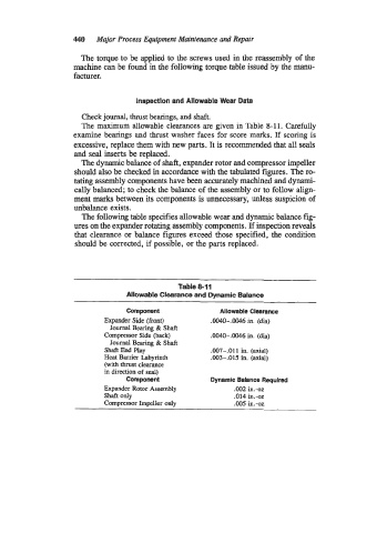
The following table specifies allowable wear and dynamic balance fig-
ures on the expander rotating assembly components. If inspection reveals
that clearance or balance figures exceed those specified, the condition
should be corrected, if possible, or the parts replaced.
Table 8-1 1
Allowable Clearance and Dynamic Balance
Component Allowable Clearance
Expander Side (front) .0040-.0046 in. (dia)
Journal Bearing & Shaft
Compressor Side (back) .0040-.0046 in. (dia)
Journal Beating & Shaft
Shaft End Play .007-.011 in. (axial)
Heat Barrier Labyrinth .003-.015 in. (axial)
(with thrust clearance
in direction of seal)
Component Dynamic Balance Requlred
Expander Rotor Assembly .002 in.432
shaft only .014 in.-oz
Compressor Impeller only .005 in.-oz