
Page 64 - Practical Machinery Management for Process Plants Major Process Equipment Maintenance and Repair
P. 64
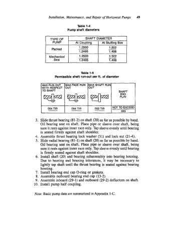
Insrailation, Mainenunce, and Repair of Horizonral PMmpS   49

                                               Tgble 1-4
                                         Pump shaft dlameters


                               TYPE OF              SHAFT DIAMETER
                                PUMP          At Coupling     At Stuffing Box
                                                1.2500            -
                                                                  1.502
                                Packed
                                                1.2495            1.498
                                                                  1.502
                              Mechanical        1.2500            -
                                 Seal           1.2495            1.498

                                                 Table 1-5
                                  Permissible shaft run-out per ft. of diameter


                          TO SHAFT


                      3.  Slide thrust bearing (81-2) on shaft (20) as far as possible by hand.
                         Oil bearing seat on shaft. Place pipe or sleeve over shaft, being
                         sure it rests against inner race only. Tap sleeve evenly until bearing
                         is seated firmly against shaft shoulder.
                      4.  Assemble thrust bearing lock washer (31) and lock nut (21-4).
                      5.  Slide radial bearing (8 1 - 1) on shaft (20) as far as possible by hand.
                         Oil bearing seat on shaft. Place pipe or sleeve over shaft, being
                         sure it rests against inner race only. 'Ihp sleeve evenly until bearing
                         is firmly seated against shaft shoulder.
                      6.  Install shaft (20) and bearing subassembly into bearing housing.
                         Due to bearing and housing tolerances, it may be necessary to
                         lightly tap shaft until the thrust bearing is seated against bearing
                         housing.
                      7.  Install bearing end cap O-ring or gaskets.
                      8.  Assemble outboard bearing end cap (13-2).
                      9.  Assemble inboard (29-1) and outboard (29-2) deflectors on shaft.
                     10.  Install pump half coupling.

                                                   .
                      Note:  Basic pump data are summanzed in Appendix 1-C.