
Page 150 - Practical Power System and Protective Relays Commissioning
P. 150
Gas Insulated System Substations Chapter | 14 149
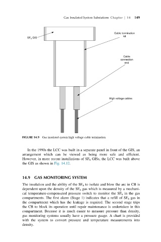
FIGURE 14.9 Gas insulated system high voltage cable termination.
In the 1990s the LCC was built in a separate panel in front of the GIS, an
arrangement which can be viewed as being more safe and efficient.
However, in more recent installations of SF 6 GISs, the LCC was built above
the GIS as shown in Fig. 14.12.
14.9 GAS MONITORING SYSTEM
The insulation and the ability of the SF 6 to isolate and blow the arc in CB is
dependent upon the density of the SF 6 gas which is measured by a mechani-
cal temperature-compensated pressure switch to monitor the SF 6 in the gas
compartments. The first alarm (Stage 1) indicates that a refill of SF 6 gas in
the compartment which has the leakage is required. The second stage trips
the CB to block its operation until repair maintenance is undertaken in this
compartment. Because it is much easier to measure pressure than density,
gas monitoring systems usually have a pressure gauge. A chart is provided
with the system to convert pressure and temperature measurements into
density.