
Page 152 - Practical Power System and Protective Relays Commissioning
P. 152
Gas Insulated System Substations Chapter | 14 151
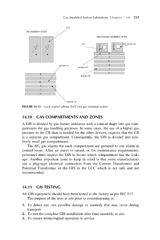
FIGURE 14.12 Local control cabinet (LCC) for gas insulated system.
14.10 GAS COMPARTMENTS AND ZONES
A GIS is divided by gas barrier insulators with a conical shape into gas com-
partments for gas handling purposes. In some cases, the use of a higher gas
pressure in the CB than is needed for the other devices, requires that the CB
is a separate gas compartment. Consequently, the GIS is divided into rela-
tively small gas compartments.
The SF 6 gas alarms for each compartment are grouped to one alarm in
control room. After an alarm is raised, or for maintenance requirements,
personnel must inspect the GIS to locate which compartment has the leak-
age. Another important issue to keep in mind is that some manufacturers
use a plug-type electrical connection from the Current Transformer and
Potential Transformer in the GIS to the LCC which is not safe and not
recommended.
14.11 GIS TESTING
All GIS equipment should have been tested at the factory as per IEC 517.
The purpose of the tests at site prior to commissioning is:
1. To detect any rare possible damage or anomaly that may occur during
transport.
2. To test the complete GIS installation after final assembly at site.
3. To ensure uninterrupted operation in service.