
Page 148 - Practical Power System and Protective Relays Commissioning
P. 148
Gas Insulated System Substations Chapter | 14 147
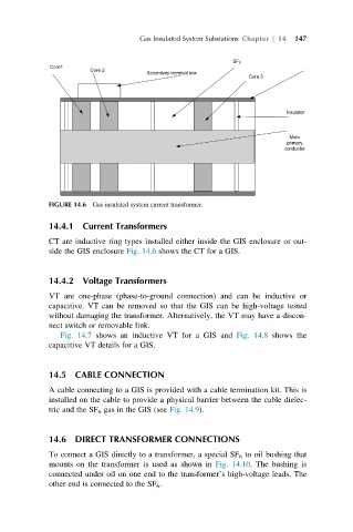
FIGURE 14.6 Gas insulated system current transformer.
14.4.1 Current Transformers
CT are inductive ring types installed either inside the GIS enclosure or out-
side the GIS enclosure Fig. 14.6 shows the CT for a GIS.
14.4.2 Voltage Transformers
VT are one-phase (phase-to-ground connection) and can be inductive or
capacitive. VT can be removed so that the GIS can be high-voltage tested
without damaging the transformer. Alternatively, the VT may have a discon-
nect switch or removable link.
Fig. 14.7 shows an inductive VT for a GIS and Fig. 14.8 shows the
capacitive VT details for a GIS.
14.5 CABLE CONNECTION
A cable connecting to a GIS is provided with a cable termination kit. This is
installed on the cable to provide a physical barrier between the cable dielec-
tric and the SF 6 gas in the GIS (see Fig. 14.9).
14.6 DIRECT TRANSFORMER CONNECTIONS
To connect a GIS directly to a transformer, a special SF 6 to oil bushing that
mounts on the transformer is used as shown in Fig. 14.10. The bushing is
connected under oil on one end to the transformer’s high-voltage leads. The
other end is connected to the SF 6 .