
Page 210 - Practical Power System and Protective Relays Commissioning
P. 210
210 Practical Power System and Protective Relays Commissioning
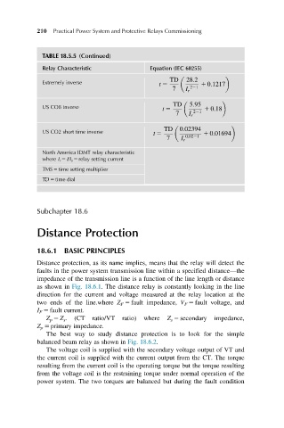
TABLE 18.5.5 (Continued)
Relay Characteristic Equation (IEC 60255)
TD 28:2
Extremely inverse t 5 1 0:1217
7 I r 221
TD 5:95
US CO8 inverse t 5 1 0:18
7 I r 221
TD 0:02394
US CO2 short time inverse t 5 1 0:01694
7 I r 0:0221
North America IDMT relay characteristic
where I r 5 I/I s 5 relay setting current
TMS 5 time setting multiplier
TD 5 time dial
Subchapter 18.6
Distance Protection
18.6.1 BASIC PRINCIPLES
Distance protection, as its name implies, means that the relay will detect the
faults in the power system transmission line within a specified distance—the
impedance of the transmission line is a function of the line length or distance
as shown in Fig. 18.6.1. The distance relay is constantly looking in the line
direction for the current and voltage measured at the relay location at the
two ends of the line.where Z F 5 fault impedance, V F 5 fault voltage, and
I F 5 fault current.
Z p 5 Z s . (CT ratio/VT ratio) where Z s 5 secondary impedance,
Z p 5 primary impedance.
The best way to study distance protection is to look for the simple
balanced beam relay as shown in Fig. 18.6.2.
The voltage coil is supplied with the secondary voltage output of VT and
the current coil is supplied with the current output from the CT. The torque
resulting from the current coil is the operating torque but the torque resulting
from the voltage coil is the restraining torque under normal operation of the
power system. The two torques are balanced but during the fault condition