
Page 211 - Practical Power System and Protective Relays Commissioning
P. 211
Protection Relays Chapter | 18 211
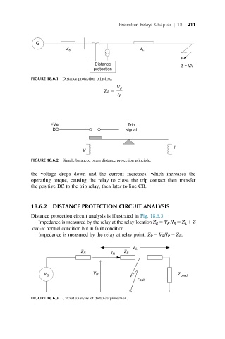
FIGURE 18.6.1 Distance protection principle.
V F
Z F 5
I F
FIGURE 18.6.2 Simple balanced beam distance protection principle.
the voltage drops down and the current increases, which increases the
operating torque, causing the relay to close the trip contact then transfer
the positive DC to the trip relay, then later to line CB.
18.6.2 DISTANCE PROTECTION CIRCUIT ANALYSIS
Distance protection circuit analysis is illustrated in Fig. 18.6.3.
Impedance is measured by the relay at the relay location Z R 5 V R /I R 5 Z L 1 Z
load-at normal condition but in fault condition.
Impedance is measured by the relay at relay point: Z R 5 V R /I R 5 Z F .
FIGURE 18.6.3 Circuit analysis of distance protection.