
Page 263 - Practical Power System and Protective Relays Commissioning
P. 263
260 Practical Power System and Protective Relays Commissioning
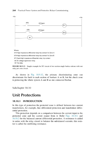
FIGURE 18.9.13 Simple example for DC circuit of two section single busbar scheme with one
relay per zone circuit.
As shown in Fig. 18.9.12, the primary discriminating zone can
discriminate the fault in each section of busbars A or B, but the check zone
is protecting the whole system A and B as one connected busbar.
Subchapter 18.10
Unit Protections
18.10.1 INTRODUCTION
In this type of protection the protected zone is defined between two current
transformers, for example, line differential protection and transformer differ-
ential protection.
This protection depends on a comparison between the current input to the
protected zone and the current output from it. Refer Figs. 18.10.1 and
18.10.2 for the balanced current differential protection. A resistance is added
in series with the relay circuit to balance the unbalanced currents; this resis-
tor is called the stabilizing resistance.