
Page 258 - Practical Power System and Protective Relays Commissioning
P. 258
Protection Relays Chapter | 18 255
18.9.3.3.1 Low-Impedance Busbar Prottection
Low-impedance busbar protection uses the Merz-price circulating current
principle for biased differential protection to detect a fault in the busbar
zone, as shown in Fig. 18.9.5.
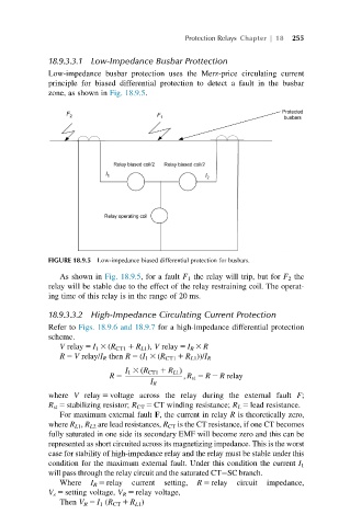
FIGURE 18.9.5 Low-impedance biased differential protection for busbars.
As shown in Fig. 18.9.5, for a fault F 1 the relay will trip, but for F 2 the
relay will be stable due to the effect of the relay restraining coil. The operat-
ing time of this relay is in the range of 20 ms.
18.9.3.3.2 High-Impedance Circulating Current Protection
Refer to Figs. 18.9.6 and 18.9.7 for a high-impedance differential protection
scheme.
V relay 5 I 1 3 (R CT1 1 R L1 ), V relay 5 I R 3 R
R 5 V relay/I R then R 5 (I 1 3 (R CT1 1 R L1 ))/I R
I 1 3 ðR CT1 1 R L1 Þ
R 5 ; R st 5 R 2 R relay
I R
where V relay 5 voltage across the relay during the external fault F;
R st 5 stabilizing resistor; R CT 5 CT winding resistance; R L 5 lead resistance.
For maximum external fault F, the current in relay R is theoretically zero,
where R L1 , R L2 are lead resistances, R CT is the CT resistance, if one CT becomes
fully saturated in one side its secondary EMF will become zero and this can be
represented as short circuited across its magnetizing impedance. This is the worst
case for stability of high-impedance relay and the relay must be stable under this
condition for the maximum external fault. Under this condition the current I 1
will pass through the relay circuit and the saturated CT SC branch.
Where I R 5 relay current setting, R 5 relay circuit impedance,
V s 5 setting voltage, V R 5 relay voltage,
Then V R 5 I 1 (R CT 1 R L1 )