
Page 255 - Practical Power System and Protective Relays Commissioning
P. 255
252 Practical Power System and Protective Relays Commissioning
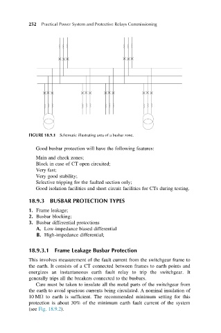
FIGURE 18.9.1 Schematic illustrating area of a busbar zone.
Good busbar protection will have the following features:
Main and check zones;
Block in case of CT open circuited;
Very fast;
Very good stability;
Selective tripping for the faulted section only;
Good isolation facilities and short circuit facilities for CTs during testing.
18.9.3 BUSBAR PROTECTION TYPES
1. Frame leakage;
2. Busbar blocking;
3. Busbar differential protections
A. Low-impedance biased differential
B. High-impedance differential;
18.9.3.1 Frame Leakage Busbar Protection
This involves measurement of the fault current from the switchgear frame to
the earth. It consists of a CT connected between frames to earth points and
energizes an instantaneous earth fault relay to trip the switchgear. It
generally trips all the breakers connected to the busbars.
Care must be taken to insulate all the metal parts of the switchgear from
the earth to avoid spurious currents being circulated. A nominal insulation of
10 MΩ to earth is sufficient. The recommended minimum setting for this
protection is about 30% of the minimum earth fault current of the system
(see Fig. 18.9.2).